
MIXED FLOWING GAS (MFG) TEST CHAMBERS

Auto Technology designs and builds custom Mixed Flowing Gas (MFG) corrosion test systems for contacts, connectors, electronic assemblies, and materials. Each chamber is sized around the customer’s actual specimens, required quantity, exposed surface area, spacing, and the applicable test specification, then configured for the required working volume, air exchange, gas supply, analyzers, temperature, humidity, controls, and facility requirements.
Individual mass flow controls, gas analysis, and controlled temperature and humidity work together to produce the required exposure atmosphere. Systems are designed and built in Ohio, USA, by the company operating the largest MFG testing laboratory in the USA.
Test Standards and Nominal Exposure Conditions
MFG chambers reproduce controlled corrosive atmospheres for contacts, connectors, sockets, plated surfaces, electronic assemblies, and other materials. Each system is configured around the required gas concentrations, temperature, humidity, specimen loading, monitoring, and verification requirements. See our electronics corrosion chamber overview for related electronics exposure capabilities.
Selection of mixed flowing gas exposure conditions for electrical contacts and related materials.
Chamber construction, gas delivery, airflow, operation, monitoring, and verification requirements for MFG testing.
Copper coupon preparation and mass-change measurement used to evaluate chamber corrosivity and working-volume uniformity.
Flowing mixed gas corrosion exposures for components, equipment, contacts, connections, and materials.
Flowing mixed gas corrosion testing of electrical contacts and connections used in electronic connectors.
Mixed flowing gas environmental testing of electrical connectors, contacts, and sockets.
Classification of corrosive airborne environments affecting electronic, process-control, telecommunications, networking, and data-center equipment, including evaluation using copper and silver reactivity.
Combined Operating Range Across the Specifications
| Parameter | Lowest–Highest Specified Target |
|---|---|
| Temperature | 25–50°C |
| Relative humidity | 70–75% RH |
| Hydrogen sulfide — H₂S | 10–12,500 ppb |
| Sulfur dioxide — SO₂ | 100–25,000 ppb |
| Nitrogen dioxide — NO₂ | 200–610 ppb |
| Chlorine — Cl₂ | 3–50 ppb |
| Chamber air exchange | 3–12 volume changes per hour* |
These ranges show the lowest and highest nominal conditions found across the reviewed ASTM B845, IEC 60068-2-60, IEC 60512-11-7, and EIA-364-65 exposure methods, including the ASTM single-gas exposures. The endpoints do not occur together as one test condition. Each method uses its own combination of temperature, humidity, gas concentrations, air exchange, tolerances, monitoring, and verification requirements. *Air exchange is method-specific: IEC 60068-2-60 specifies 3–10 volume changes per hour for Methods 1–4, while EIA-364-65C requires 6–12 changes per hour and requires the exchange rate to remain within ±5%. ASTM methods establish airflow and exchange requirements according to the selected exposure and chamber-performance requirements. These are method requirements and nominal setpoints, not a statement of the operating limits of every chamber.

View Method Conditions and System Requirements
Values below are nominal exposure targets. Each method defines its applicable tolerances, air exchange, duration, monitoring, and verification requirements.
| Method | Temperature / RH | Gas Targets | System Configuration Considerations |
|---|---|---|---|
| ASTM B845 A | 25°C; 75% RH | SO₂ 25,000 ppb | High-concentration single-gas supply and analysis |
| ASTM B845 B | 25°C; 75% RH | H₂S 12,500 ppb | High-concentration single-gas supply and analysis |
| ASTM B845 C / D | 25°C; 75% RH | C: SO₂ 500 ppb; D: H₂S 100 ppb | Single-gas delivery and measurement |
| ASTM B845 E / IEC Method 1 | 25°C; 75% RH | H₂S 100; SO₂ 500 ppb | Two-gas delivery and method-specific verification |
| ASTM B845 G / IEC Method 2 | 30°C; 70% RH | H₂S 10; NO₂ 200; Cl₂ 10 ppb | Low-level H₂S and chlorine measurement |
| ASTM B845 H / IEC Method 3 | 30°C; 75% RH | H₂S 100; NO₂ 200; Cl₂ 20 ppb | Three-gas delivery and measurement |
| ASTM B845 K | 50°C; 75% RH | H₂S 200; NO₂ 200; Cl₂ 50 ppb | 50°C environmental capability and condensation-managed sampling |
| ASTM B845 L | 30°C; 70% RH | H₂S 40; SO₂ 350; NO₂ 610; Cl₂ 3 ppb | Four-gas measurement including low-level chlorine |
| ASTM B845 M / IEC Method 4 | 25°C; 75% RH | H₂S 10; SO₂ 200; NO₂ 200; Cl₂ 10 ppb | Four-gas delivery, monitoring, and verification |
| ASTM B845 N | 30°C; 70% RH | H₂S 10; SO₂ 200; NO₂ 200; Cl₂ 10 ppb | Four-gas delivery and concentration monitoring |
| ASTM B845 O / EIA Class IIA | 30°C; 70% RH | H₂S 10; SO₂ 100; NO₂ 200; Cl₂ 10 ppb | Four-gas delivery, monitoring, and coupon verification |
| ASTM B845 P / EIA Class IIIA | 30°C; 70% RH | H₂S 100; SO₂ 200; NO₂ 200; Cl₂ 20 ppb | Four-gas delivery, monitoring, and coupon verification |
| EIA Class IV | 40°C; 75% RH | H₂S 200; NO₂ 200; Cl₂ 30 ppb | 40°C environmental capability and three-gas measurement |
| IEC 60512-11-7 | Methods 1–4: 25°C or 30°C; 70% or 75% RH | Corresponding IEC mixture shown above | Connector preparation, exposure, and evaluation |
| ASTM B845 X | As specified | As specified | Custom exposure parameters agreed for the test program |
Mixed flowing gas exposure is also used within broader connector and electronic-product qualification programs. USB cable and connector qualification, including USB Type-C requirements associated with IEC 62680-1-3, can include MFG exposure. UL certification may also be part of an overall product qualification program; when MFG exposure is required, the chamber is configured to the applicable MFG test method or connector specification.
Grouped rows share nominal setpoints, but tolerances and test procedures remain specific to the governing standard. ASTM B845 Method K and EIA Class IV use different exposure conditions.
Industries and MFG Applications
Mixed flowing gas testing is used where electrical contacts, plated surfaces, connectors, and electronic assemblies may be exposed to low concentrations of corrosive airborne contaminants. Chamber size and configuration are built around the customer’s components, test specification, and required exposure.
Electronics and Components
Contacts, sockets, switches, circuit assemblies, plated surfaces, and other electronic components where low-level atmospheric corrosion can affect electrical performance or material condition.
Connectors and Interconnects
Mated and unmated connectors, terminals, sockets, contacts, cable assemblies, and other interconnect hardware tested to IEC, EIA, ASTM, USB, and customer qualification requirements.
Telecommunications and Networking
Connector systems, networking equipment, communications hardware, and electronics intended for environments where airborne sulfur and chlorine compounds can contribute to corrosion.
Data Centers and IT Equipment
Electronic hardware evaluated for corrosive environmental severity, including applications where copper and silver reactivity are used to characterize the installation environment.
Industrial and Process Control
Controls, instrumentation, electrical connections, and electronic assemblies used in industrial environments where corrosive airborne contaminants can affect reliability.
Automotive and Transportation Electronics
Electrical connectors, terminals, control modules, sensors, and other electronic hardware subjected to customer or component-level corrosion qualification programs.
Robotics and Automation
Slip rings, connectors, relays, switches, controls, sensors, and other electrical contacts used in robots and automated equipment. Where MFG is part of the qualification program, systems can be configured to ASTM B845, ASTM B827, EIA-364-65, IEC 60068-2-60, or customer requirements.
Defense and Aerospace Electronics
Connectors, contacts, avionics hardware, control electronics, and other assemblies used in defense and aerospace programs. When mixed flowing gas exposure is specified by a component, connector, contract, or customer requirement, the chamber is built around the applicable ASTM, EIA, IEC, or program-specific MFG method.
Independent Testing and Research Laboratories
Contract testing laboratories, corporate product-development labs, and university research groups evaluating specimens for different customers or research programs. Systems are configured around the required methods, specimen sizes, test capacity, instrumentation, and records.
Energy and Electrical Infrastructure
Connectors, relay contacts, controls, and electronics used in power generation, distribution, renewable-energy equipment, and charging systems. MFG exposure can be incorporated where corrosive-gas testing is relevant to the application or required by the product specification.
Appliances and Building Systems
Switches, connectors, controls, and electronics used in HVAC equipment, appliances, building automation, and security systems. Chambers are configured for the applicable corrosive-gas exposure methods and specimen requirements.
Chamber Construction and Control Configurations
Chamber size, gas delivery, instrumentation, and controls are selected as one system. Physical fit is only the starting point. The design also accounts for specification-defined specimen loading, exposed surface area, spacing, fixture layout, qualified working volume, required air exchange, gas absorption, access, and available laboratory space.
Custom Test Space and Specimen Loading
MFG chamber size is not determined only by whether the specimens physically fit inside the enclosure. The applicable test specification can also limit specimen loading, spacing, working volume, and the amount of test atmosphere that must pass through the chamber.
Chambers are therefore sized around the actual specimens, required quantity, exposed surface area, fixtures, spacing, applicable MFG method, qualified working volume, and required air exchange. Systems range from compact laboratory chambers to custom walk-in MFG chambers .
| Specification | Sizing / Loading Consideration | Air Exchange |
|---|---|---|
| IEC 60068-2-60 | Total specimen volume should not exceed 10% of the working-area volume, and total specimen surface area should not exceed 10% of the working-area surface area. Amounts above 10% must be reported. Approximately 10 mm spacing between specimens is suggested to avoid disturbing uniform airflow. | 3–10 volume changes per hour for Methods 1–4 |
| EIA-364-65C | No fixed specimen-volume percentage is specified. Specimens must be at least 5 cm (2 in.) from the chamber walls and arranged to minimize obstruction of airflow. The chamber working volume must be qualified. | 6–12 volume changes per hour, maintained within ±5% |
| ASTM B827 / B845 | No universal chamber-to-specimen volume ratio applies to every ASTM MFG method. Chamber loading must allow the required gas concentrations and flow uniformity to be maintained. Excessive inlet-to-outlet gas loss can indicate excessive specimen loading. | Method- and performance-dependent |
The qualified working volume is not necessarily the same as the chamber's total internal volume. Final chamber dimensions and specimen capacity are established from the governing test method, specimen geometry and loading, fixtures, airflow requirements, coupon locations, loading access, and facility constraints. IEC's 10% loading guidance should not be applied as a universal MFG chamber-to-sample ratio.

Dual-Chamber Construction
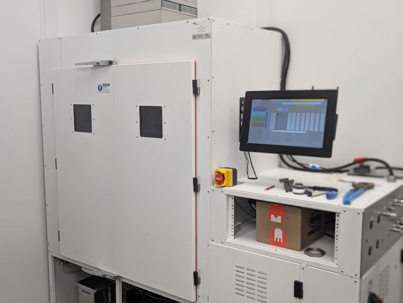
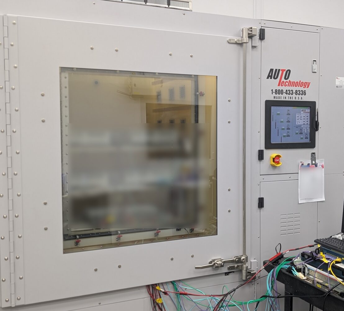
The inner chamber contains the controlled gas exposure. The surrounding outer chamber helps stabilize temperature around the exposure enclosure and provides an additional safety enclosure. Both chambers are connected to the ventilation system.
Chambers are built to the selected MFG specifications, including a nonreactive, low-absorbing, nonmetallic exposure enclosure within a temperature-controlled cabinet. Gas-contact materials, seals, tubing, and mixing arrangements are selected to limit gas loss and maintain uniform exposure in accordance with ASTM B827 requirements.

Ventilation for Both Chambers
Separate ventilation paths serve the inner exposure chamber and the outer enclosure. The chamber connects to the facility exhaust system so test gases can be removed and the system can be purged after testing. Differential-pressure monitoring detects exhaust backpressure, and the required exhaust capacity is established for each build.

Mass Flow Controls, Air Exchange, and Gas Supply
Each test gas is metered independently through its own mass flow controller. Metering ranges and dilution are selected around the required chamber concentrations, chamber volume, specified air-exchange rate, and the gas-cylinder concentrations accepted by the facility. Gas analyzers then measure the resulting concentrations inside the exposure chamber.
Air exchange is the controlled introduction and exhaust of test atmosphere through the chamber and is separate from internal circulation used to distribute that atmosphere. Depending on the governing method, the required exchange rate may be specified directly. IEC 60068-2-60 uses 3–10 volume changes per hour for Methods 1–4, while EIA-364-65C requires 6–12 changes per hour and requires that rate to remain within ±5%.
Specimen loading also affects gas-system sizing because specimens, fixtures, and chamber surfaces can absorb or react with pollutant gases. ASTM B827 requires the chamber and gas supply to maintain the specified atmosphere through the usable working volume and uses inlet-to-outlet gas concentration as a check on chamber loading and gas delivery. Excessive concentration loss can indicate excessive loading or insufficient exchange. ASTM B827 also limits chamber leakage and defines requirements for gas-flow uniformity.


Gas Monitoring: Switching and Dedicated Analyzers
Gas analyzers measure the actual exposure concentrations in the chamber. Integrated systems display and record analyzer readings through the PC. Analyzer ranges, accuracy, resolution, response time, and gas compatibility are selected around the required test conditions, particularly for low-concentration gases where the analyzer must provide useful accuracy at the specified exposure level.
Switching analyzers measure compatible gases sequentially. For example, a Serinus 51 switches between hydrogen sulfide and sulfur dioxide measurement modes, with time allowed for each reading to stabilize. Dedicated analyzers provide separate instruments for the specified gases. Instrument selection and sampling frequency follow the test method and required measurement performance.
Chlorine measurement is configured for the selected method because other gases and humidity can affect the reading. Where specified, analyzer feedback can also be used to automatically adjust gas delivery and maintain the required chamber concentration.

Computer Controls
A panel-mounted PC running custom LabVIEW software brings gas flow settings, analyzer readings, test recipes, sequencing, trends, records, and alarms into one interface. Operators can adjust gas delivery manually or use analyzer feedback for automatic concentration control where specified. Ethernet communication supports analyzer integration and configured remote status functions.

Temperature and Humidity Stabilization and Control
The outer chamber surrounds the inner exposure enclosure and helps stabilize its temperature. Controlling the conditions around the exposure chamber helps maintain uniform test conditions and reduces the risk of condensation that could remove gases from the atmosphere.
Temperature and humidity can be controlled independently through dedicated controls or integrated into the computer control system. Inner and outer chamber probes provide the environmental measurements used by the selected control arrangement.


Options and Test Verification
Application-Specific Options
- Specimen racks, shelves, hangers, and custom fixtures.
- Wiring ports for external instruments and connected specimens.
- Additional test gases and custom mixtures, with compatible delivery and analyzer equipment.
- Permeation-tube gas supply where specified.
- Project-specific field inspection, including optional NRTL field inspection.
Chamber Verification with Copper Coupons
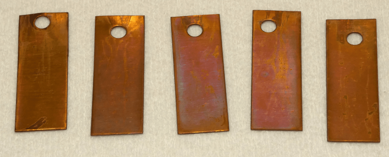
Gas analyzers verify the concentration of the individual gases. Copper coupons provide a separate check of the corrosive effect produced by the combined atmosphere and are used to evaluate uniformity throughout the working space.
Coupons are cleaned, weighed, positioned throughout the chamber, exposed, and weighed again so mass gain can be compared by location. ASTM B810 provides the mass-change procedure for ASTM chamber verification and is referenced by EIA-364-65 for working-volume qualification. Coupon preparation and evaluation follow the governing test method, including the specific procedures in IEC 60068-2-60 and EIA-364-65 where applicable.
New chambers are profiled before being placed into service, and chambers are rechecked after structural changes that could affect gas flow. Coupon results are compared across the working space to establish the usable test volume in accordance with ASTM B827 requirements. Corrosivity monitors are also used during individual test runs; initial chamber profiling does not replace ongoing test verification.
Laboratory and Installation Requirements
Each system is supplied with installation requirements based on chamber size, gas supply, environmental controls, analyzers, and the selected test methods. Gas, electrical, exhaust, water, networking, space, and room-condition requirements are coordinated with the facility during the design process.
| Requirement | Project Planning |
|---|---|
| Gas supply | Gas types, cylinder concentrations, regulators, and connections selected for the test and facility requirements |
| Clean dry air | Air quality, pressure, and capacity established for the method and gas delivery system |
| Humidifier water | Water quality selected to meet the applicable method requirements |
| Electrical power | Voltage, frequency, and circuit capacity defined for the complete system |
| Exhaust ventilation | Exhaust capacity and connections established for inner and outer chamber ventilation and facility treatment requirements |
| Space and access | System footprint, installation route, specimen loading, and service clearances established for the layout |
| Room conditions | Permitted room temperature, humidity, and fluctuations defined for the completed installation |
| Networking | Connections coordinated for analyzer communications and configured remote status functions |
Interlocks, Warnings, and Fault Monitoring
The controls monitor the conditions needed to operate the chamber safely and maintain the programmed exposure. Exhaust differential pressure detects vent backpressure, while the system reports environmental deviations, flow warnings, controller faults, and other conditions requiring attention.
Operating Warnings
- Temperature outside the configured limits
- Relative humidity outside the configured limits
- Mass flow controller warnings
- Controller and humidification system warnings
Fault Monitoring
- Exhaust differential-pressure faults
- Water leak detection
- Controller faults
- Emergency stop
- Gas-generation bath faults when a permeation system is fitted
Project-specific safety review and optional NRTL field inspection can be included when required.
Frequently Asked Questions
When should mixed flowing gas testing be used instead of salt spray testing?
MFG testing exposes specimens to controlled concentrations of corrosive gases at a specified temperature and humidity. It is used to evaluate electrical contacts, connectors, plated surfaces, and electronics where gaseous pollutants are part of the expected exposure or qualification requirement.
Salt spray testing exposes specimens to a salt-containing fog and produces a different corrosion environment. Select the test according to the expected service conditions and governing specification; the two methods are not interchangeable.
What should be planned for commissioning and operator training?
The project review should establish facility readiness, installation responsibilities, chamber verification, and operator training before delivery. Training topics should include gas supply and changeout, test setup, analyzer checks, coupon handling, records, alarms, and shutdown procedures. Confirm the commissioning and training scope in the quotation.
What routine calibration and maintenance does an MFG system require?
Plan for analyzer calibration and verification, temperature and humidity instrument checks, and inspection of gas delivery, humidification, and exhaust components. Gas cylinders and consumables also need replacement as required. The schedule depends on the selected instruments, operating hours, and test method.
Copper-coupon verification checks chamber corrosivity and uniformity; it does not replace instrument calibration. Follow the equipment instructions and the governing test method for both.
How are service, replacement parts, and troubleshooting arranged?
Review service arrangements and replacement-part needs when specifying the chamber. Identify the chamber and analyzer models, required consumables, recommended spare parts, and responsibilities for instrument service. Confirm available troubleshooting support and service arrangements with Auto Technology as part of the quotation.
Can we test specimens before specifying a chamber?
Our MFG laboratory can review a test program using your specimens and required exposure method. Testing can help inform specimen handling, fixtures, and measurement needs before you finalize a chamber purchase. Contact us to review laboratory capacity, specimen fit, and the proposed test conditions.
What determines delivery time for a custom MFG chamber?
Delivery time depends on chamber size, gas and analyzer configuration, controls, custom fixtures, and component availability. Facility requirements and any project-specific inspection or acceptance testing also affect the schedule. Request a project-specific lead time with your quotation.
How are temperature, humidity, and gas concentrations controlled?
Temperature and humidity can use dedicated controls or the PC, depending on the system configuration. Individual mass flow controllers meter the test gases, while gas analyzers measure the actual chamber concentrations. Analyzer feedback can also be used for automatic concentration adjustment where specified.
How is the chamber size determined?
Chamber size starts with specimen dimensions, quantity, fixtures, and loading access, but the applicable test specification can also establish limits on specimen loading, spacing, qualified working volume, and air exchange.
For example, IEC 60068-2-60 recommends that total specimen volume remain at or below 10% of the working-area volume and separately recommends that total specimen surface area remain at or below 10% of the working-area surface area. EIA-364-65C does not use that percentage; instead it requires wall clearance, minimized airflow obstruction, a qualified working volume, and 6–12 chamber changes per hour.
We therefore size the chamber and gas-delivery system together rather than selecting an enclosure based only on whether the parts physically fit. Larger systems can also be built as walk-in MFG chambers .
Does gas cylinder size or concentration affect chamber operation?
Cylinder size primarily determines how long the gas supply lasts between replacements. With the same gas mixture and a compatible regulated supply, a larger cylinder generally does not require different chamber settings.
Gas concentration affects the delivery flow needed to achieve the specified chamber atmosphere. Higher-concentration mixtures require less flow; lower-concentration mixtures require more. We select mass flow controller ranges and dilution arrangements around the supply concentrations accepted by your facility and the required test conditions.
What is the difference between switching and dedicated analyzers?
Switching analyzers measure compatible gases sequentially. For example, a Serinus 51 switches between hydrogen sulfide and sulfur dioxide measurement modes. Dedicated analyzers provide separate instruments for the specified gases. The configuration depends on the required accuracy, response time, sampling frequency, gas compatibility, and test method.
Can you configure the system for other gases?
Standard MFG configurations use hydrogen sulfide, sulfur dioxide, nitrogen dioxide, and chlorine. Other gases and custom mixtures can be reviewed for the application, with compatible materials, delivery hardware, and measurement equipment selected accordingly.
How are airflow and air exchange determined?
The required chamber exchange rate comes from the selected test method. IEC 60068-2-60 specifies 3–10 volume changes per hour for Methods 1–4, while EIA-364-65C requires 6–12 changes per hour and requires the rate to remain within ±5%.
Air exchange is different from internal circulation. Exchange describes test atmosphere entering and leaving the exposure chamber; internal circulation distributes that atmosphere through the working volume. Chamber volume, specimen loading, fixtures, gas absorption, and the required pollutant concentrations are considered when sizing the air, gas-delivery, and exhaust systems.
How do you verify that the required atmosphere is being achieved?
Gas analyzers measure the individual exposure concentrations. Temperature and humidity instrumentation confirms the environmental conditions, while copper control coupons provide an independent measure of the corrosive effect and exposure uniformity. Our MFG testing laboratory uses the same basic verification principles in customer test programs.
Can specimens be wired to external equipment?
Yes. Wiring ports and specimen arrangements can be incorporated for external measurements or connected testing. The powered, mated, or unmated condition of the specimen follows the selected test method. IEC 60512-11-7 requires specimens to remain electrically unloaded during exposure.
Are MFG chambers available from stock?
No. Auto Technology MFG systems are built to order around the customer’s samples, required test methods, chamber size, instrumentation, gas supply, and facility. Our onsite chambers are operated for customer MFG testing .
Can Auto Technology perform the testing for us?
Yes. Our MFG laboratory performs customer testing . Send the test method, specimen details, exposure duration, and measurement requirements and we can review the test program.
Tell Us What You Need to Test
Send your test method, sample dimensions and quantity, exposed surface area, fixture requirements, and facility gas restrictions. We will size the chamber around the samples, specification-defined loading and air-exchange requirements, then develop the gas delivery, instrumentation, controls, and overall system configuration around the program.
Request a Custom MFG System