
SALT SPRAY / FOG & HUMIDITY CHAMBERS | M SERIES VS C SERIES
Auto Technology offers two basic salt fog / salt spray, and high humidity corrosion test chambers:
the M Series Legacy Steel Salt Fog Chamber and the
C Series Modern Fiberglass Salt Spray Chamber.
Both platforms support traditional corrosion testing,
salt solution exposure, DI water operation, ventilation planning, and humidity testing, but they differ in chamber
construction, footprint, humidity capability, cost per cubic foot, controls, and future cyclic corrosion upgrade potential.
While fiberglass chambers have become the preferred choice for many new installations, the M Series steel water-jacket design continues to serve laboratories that require a traditional ASTM B117-style chamber. ASTM B117 was originally developed around the water-jacketed steel chamber design, some legacy specifications continue to call for radiant-heated chambers rather than direct-heated or wet-bottom designs, and many laboratories prefer to maintain correlation with historical test data generated in steel chambers over decades of testing.
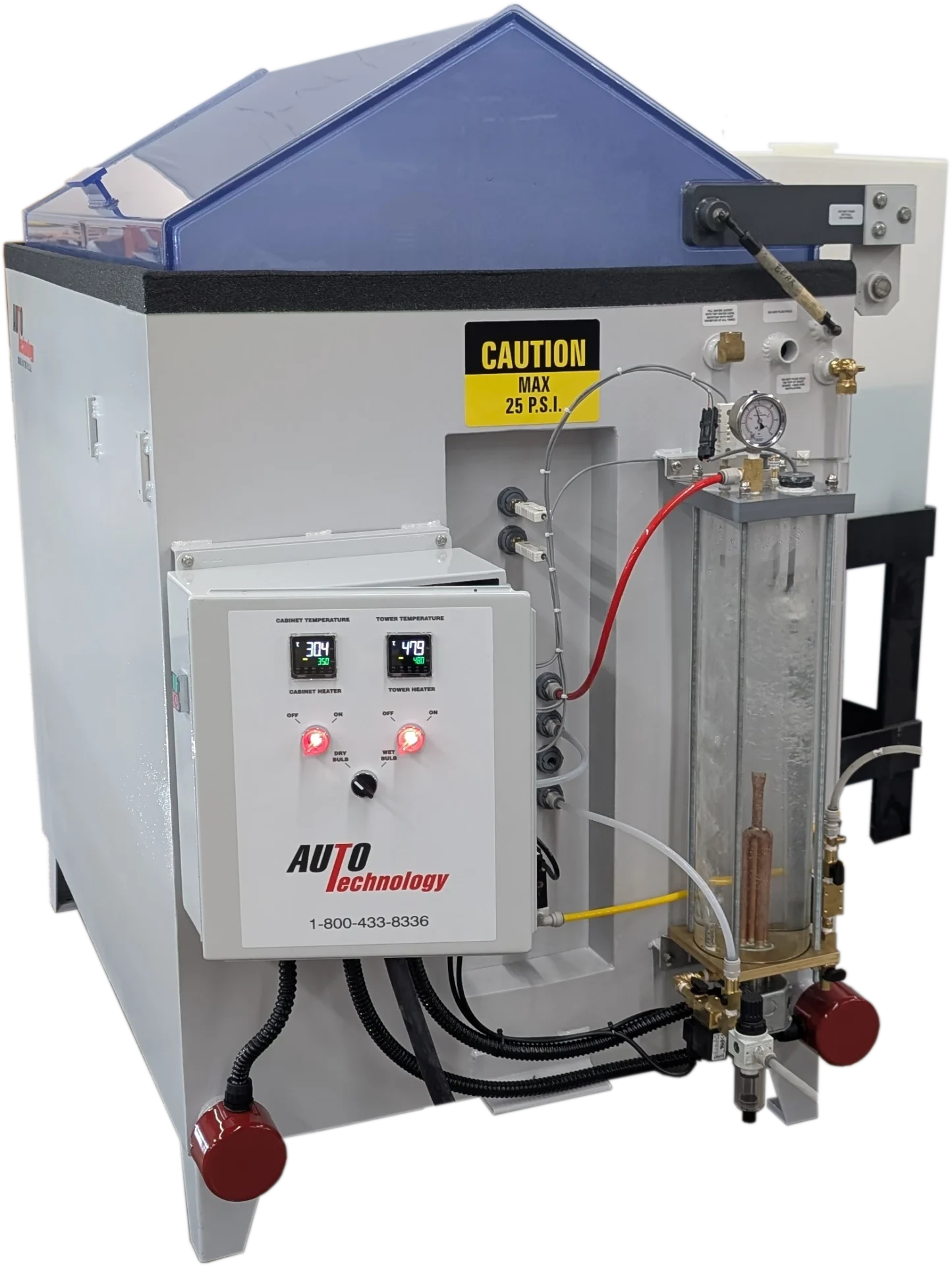
M Series Legacy Steel Salt Fog Chamber
Traditional ASTM B117 salt fog chamber.
View M Series Chamber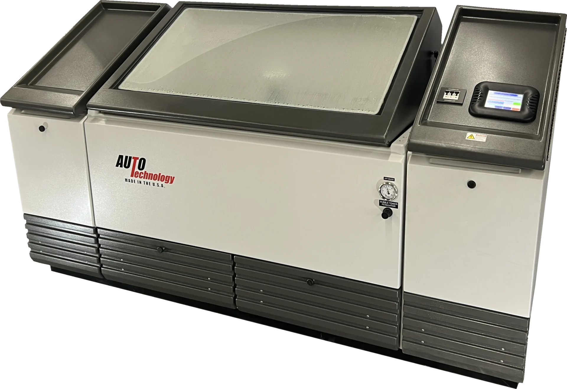
Purpose
This is THE legacy steel salt fog chamber. It is the classic water-jacketed chamber design established by ASTM B117-style salt fog practice and relied upon by manufacturers of metals, coatings, fasteners, vehicles, and industrial products for more than 75 years.
The water-jacketed design provides excellent temperature uniformity and stability throughout the exposure zone for traditional salt fog, salt spray, and water fog humidity testing.
This is a modern fiberglass salt spray and high humidity chamber with a lower cost per cubic foot, touchscreen controls, condensing humidity capability out of the box, water fog humidity capability, and limited automatic cyclic functionality.
It can be upgraded later to support future advanced cyclic corrosion testing requirements.
Space
The overall amount of space required is similar for comparably sized chambers and exposure zones.
The footprint is more flexible because the 55-gallon solution tank is detached from the chamber and can be positioned independently.
The ventilation connection is located on the side. Multiple chamber sizes are available.
The footprint is generally more fixed because the 60-gallon solution tank is attached to the chamber.
The ventilation connection is located on the rear. Two standard sizes are available.
City Water
The water jacket used to heat the chamber requires DI water and rust inhibitor.
City water is not required but may be used to fill the wet bottom.
DI Water
Both systems require ASTM D1193 Type IV water for fog generation and as a major component of the salt solution.
In addition to normal operation, DI water is generally used for the water trough lid seal.
DI water is used for normal operation.
Salt Solution
Both systems require salt solution when running salt fog tests, salt spray tests, or related corrosion test practices. Salt solution can be purchased premixed from Auto Technology Company.
Salt solution can be mixed directly in the external solution tank.
Salt solution can be mixed directly in the attached solution tank when equipped with the optional mixing tank package.
Ventilation
Both systems require a method for handling humid, salt-laden exhaust air.
The standard installation uses a ventilation line routed to the exterior of the building. A powered vent can be added for long ventilation runs.
If exterior ventilation is unavailable, scrubber options are available, including basic scrubbers, recirculating scrubbers, and advanced computer-controlled recirculating scrubbers.
Drainage
Both systems generate water-based condensate and byproducts that must be managed.
Under normal operating conditions, the chamber continuously drains a small amount of liquid while running and requires access to a suitable floor drain.
Custom drainage solutions are available for facilities with drainage limitations.
Under normal operating conditions, the chamber continuously drains a small amount of liquid while running and requires access to a suitable floor drain.
Custom drainage solutions are available for facilities with drainage limitations.
Humidity Capability
Both chamber platforms can perform humidity testing, but the method used to create humidity differs.
The M Series can perform water fog humidity testing by atomizing DI water.
Condensing humidity testing is available when equipped with an optional wet bottom and bubbler system.
The C Series can perform water fog humidity testing by atomizing DI water.
Condensing humidity testing is available out of the box because the chamber includes a wet bottom and submerged heater that continuously generates water vapor within the exposure zone.
Sample Panel Capacity
When using the Auto Technology 23" × 8.5" Slotted Test Panel Tray
- Size 15: Approximately 80 panels*
- Size 22: Approximately 200 panels*
- Size 23: Approximately 320 panels*
- Size 24: Approximately 400 panels*
- Size 20: Approximately 160 panels*
- Size 40: Approximately 360 panels*
*Approximate capacities shown are maximum capacities when using small, flat test coupons with the Auto Technology 23" × 8.5" Slotted Test Panel Tray. Larger flat panels or panels placed too closely together may create shadowing effects that interfere with proper fog exposure and reduce practical capacity.
Fiberglass vs Steel Salt Spray / Fog Chambers
The M Series uses the traditional water-jacketed steel chamber design that many established salt fog laboratories already know and trust for ASTM B117-style testing. For labs accustomed to this legacy design, the M Series often feels familiar because the chamber layout, water jacket, external solution tank, and operating approach match what they have used for years.
The C Series is a modern fiberglass salt spray and humidity chamber. It is often a better fit for laboratories that are not tied to the legacy steel chamber format and want touchscreen controls, condensing humidity capability out of the box, water fog humidity capability, and a lower cost per cubic foot.
Common Salt Fog / Spray and Humidity Chamber Applications
Neutral salt fog exposure for metals, coatings, fasteners, and assemblies.
Salt spray and salt fog corrosion testing for international qualification programs.
Humidity exposure for products, finishes, coatings, and materials.
Condensing humidity exposure available out of the box with the C Series.
Water fog humidity capability for laboratories that need basic high humidity exposure.
Corrosion testing for paints, platings, conversion coatings, and protective finishes.
Salt fog / spray and humidity exposure for screws, bolts, clips, brackets, and related hardware.
Evaluation of painted, plated, and coated substrates exposed to corrosive environments.
Salt fog / spray and humidity testing for components, materials, coatings, and assemblies.
Common Standards and Test Methods
These chamber platforms are commonly considered by laboratories running salt fog, salt spray, and high humidity exposure work. Final chamber selection should always be based on the exact standard, revision level, exposure requirements, humidity method, chamber size, and facility limitations.
Traditional neutral salt fog / spray testing.
International salt spray and salt fog / spray testing.
Water resistance testing in high humidity.
Water fog exposure for coatings and related materials.
Controlled condensation exposure for coatings.
Modified salt spray and cyclic corrosion practices where applicable.
Which Chamber Fits Your Testing Requirements?
M Series Legacy Steel Chamber
- Traditional ASTM B117-style salt fog chamber architecture
- Water-jacketed steel chamber design
- Excellent exposure-zone temperature stability
- Detached 55-gallon solution tank
- Multiple chamber sizes available
- Strong fit for traditional salt fog and water fog humidity testing
C Series Modern Fiberglass Chamber
- Modern fiberglass salt spray chamber construction
- Lower cost per cubic foot
- Touchscreen controls
- Condensing humidity out of the box
- Water fog humidity capability
- Upgrade path for future cyclic corrosion testing
Salt Fog and Salt Spray and Humidity Chamber FAQ
What is the difference between salt spray and salt fog?
In ASTM B117, the terms salt spray and salt fog are commonly used interchangeably. The standard itself is titled Standard Practice for Operating Salt Spray (Fog) Apparatus.
In practice, however, the objective of ASTM B117 is not to spray test specimens directly with a concentrated stream of atomized salt solution. Instead, the goal is to generate a fine, uniform fog throughout the exposure zone so all specimens receive consistent exposure. The standard verifies this by specifying fog collection rates at multiple locations within the chamber rather than requiring direct spray onto the samples.
Some corrosion chambers direct atomized salt solution toward the test specimens with little diffusion. Auto Technology chambers instead atomize the salt solution and pass it through carefully designed fog baffles that disperse the mist into a uniform corrosive fog before it reaches the specimens. This approach promotes more consistent exposure across the chamber while aligning with the intent of ASTM B117.
Which chamber is better for ASTM B117 salt fog / spray testing?
The M Series Salt Fog Chamber is the classic water-jacketed chamber design associated with ASTM B117-style salt fog testing. The C Series Fiberglass Salt Spray Chamber can also run basic salt fog / spray testing, but is often selected when a lab wants fiberglass construction, touchscreen controls, condensing humidity, and lower cost per cubic foot.
Which chamber is better for humidity testing?
Both chamber platforms can run water fog humidity. The C Series can also run condensing humidity testing out of the box, making it the stronger choice when high humidity exposure is a major part of the testing program.
Can the C Series run condensing humidity?
Yes. The C Series can run condensing humidity testing out of the box and can also run water fog humidity. That makes it a strong option for laboratories comparing fiberglass salt fog / spray chambers and high humidity chambers.
Can the M Series run humidity testing?
Yes. The M Series can run water fog humidity testing. It is primarily chosen as a traditional water-jacketed salt fog chamber with basic humidity exposure capability.
Which chamber has the lower cost per cubic foot?
The C Series is the lower-cost-per-cubic-foot platform. It is designed as a modern fiberglass salt spray and humidity chamber for laboratories that want touchscreen controls, humidity capability, and future upgrade potential.
Do both chambers require DI water?
Yes. Both systems require ASTM D1193 Type IV water for fog generation and as a major component of the salt solution.
Can Auto Technology provide premixed salt solutions?
Yes. Auto Technology supplies premixed corrosion test solutions for ASTM B117 / ISO 9227, ASTM G85 Annex A2, GM 14872, Ford CETP 00.00-L-467, SAE J2334, mixed chloride testing, and other corrosion methods.