
CYCLIC IMMERSION CHAMBERS
Auto Technology Cyclic Immersion Chambers are designed for laboratories that need repeatable immersion and drain cycling by moving solution between a lower supply tank and an upper test tank. Built around an immersion fill pump, drain solenoid, adjustable float switch assembly, and programmable electronic counters, this chamber supports controlled cyclic immersion testing for SAE AMS 2700 and customer-specific programs.
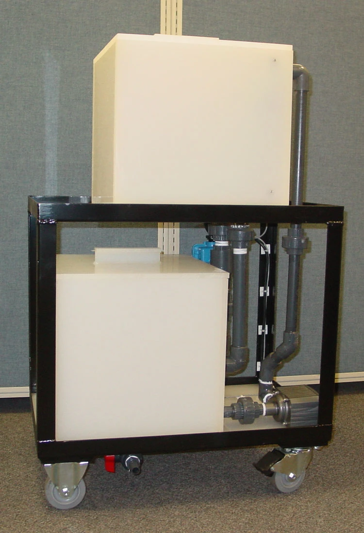
Side view highlighting the plumbing configuration and the lower 25-gallon solution reservoir.
Automated Fill and Drain Cycling
The system moves solution between the lower supply tank and upper test tank during the cyclic process.
Programmable Electronic Counters
Cycle Time, Immersion Time, and Cycle Count are controlled from the front panel.
Built to Order
Chamber size, test-space layout, and configuration depend on customer requirements.
Tell us your cycle timing, solution type, part size, and utility availability so the chamber can be configured correctly.
Overview
Auto Technology Cyclic Immersion Chambers are designed for repeated immersion exposure in which solution is moved from a lower supply tank into the upper test tank and then returned during the cyclic process. This creates a controlled immersion sequence using a fill pump, drain solenoid, float switch assembly, and programmable counters.
Unlike a simple static immersion tank, this chamber is built to support a repeated fill-and-drain test sequence. The upper chamber serves as the exposure zone while the lower tank serves as the solution reservoir between cycles.
This is a cyclic immersion system, not a continuous immersion soak tank. If your application requires constant liquid exposure without fill-and-drain cycling, see our Continuous Immersion Chambers .
During operation, the immersion fill pump moves solution from the lower supply tank into the upper test tank for immersion, and the chamber then returns the solution during the cyclic process. This fill-and-drain sequence is controlled by the electronic counters and repeated based on the programmed cycle settings.
Key Features
The chamber design centers on an upper immersion test tank, a lower solution reservoir, programmable fill and drain cycling, and front-panel timer controls.
Chamber Design
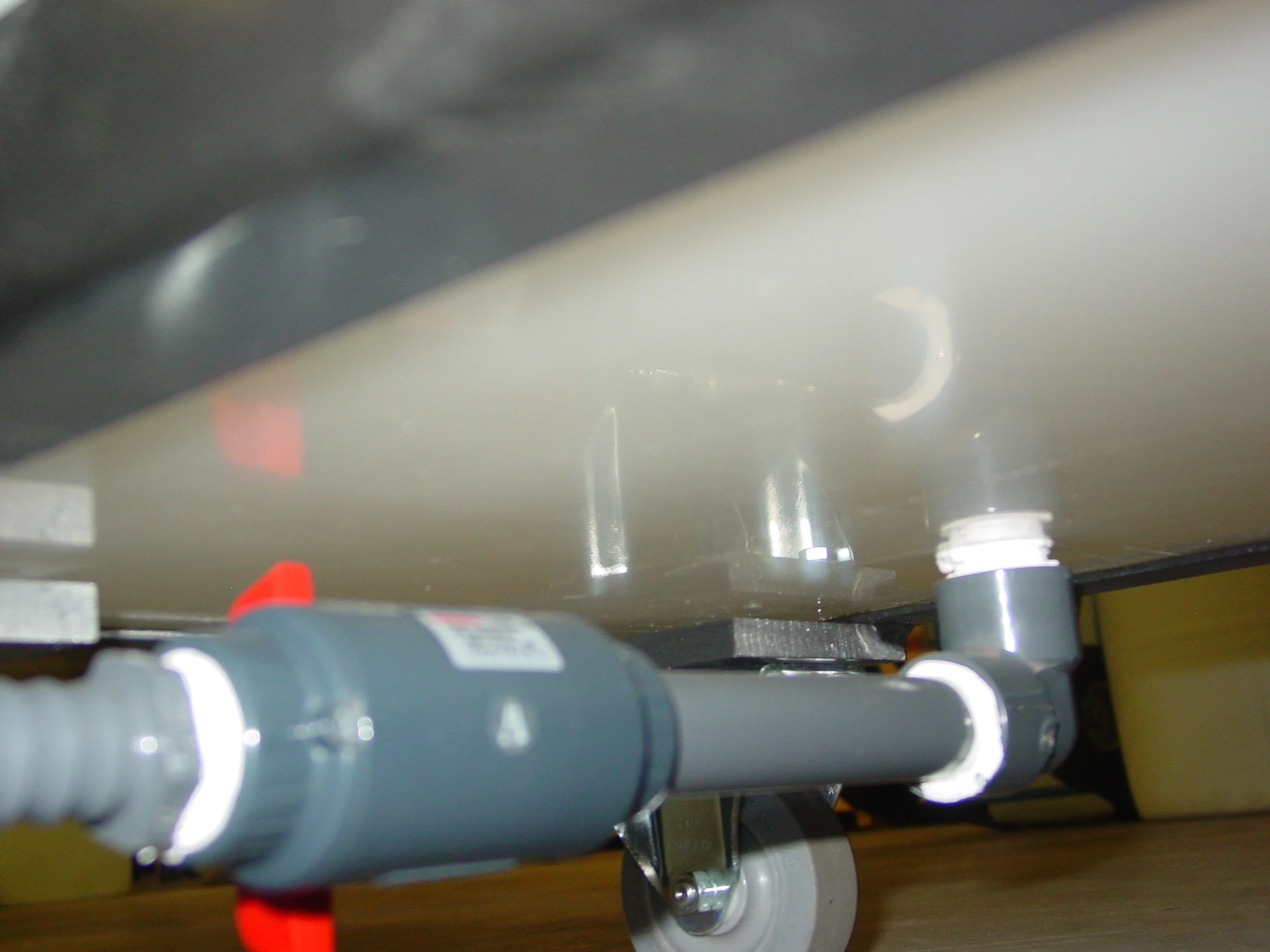
Immersion Fill Pump
The immersion fill pump is used to move solution from the lower water supply tank to the upper water test tank for immersion.
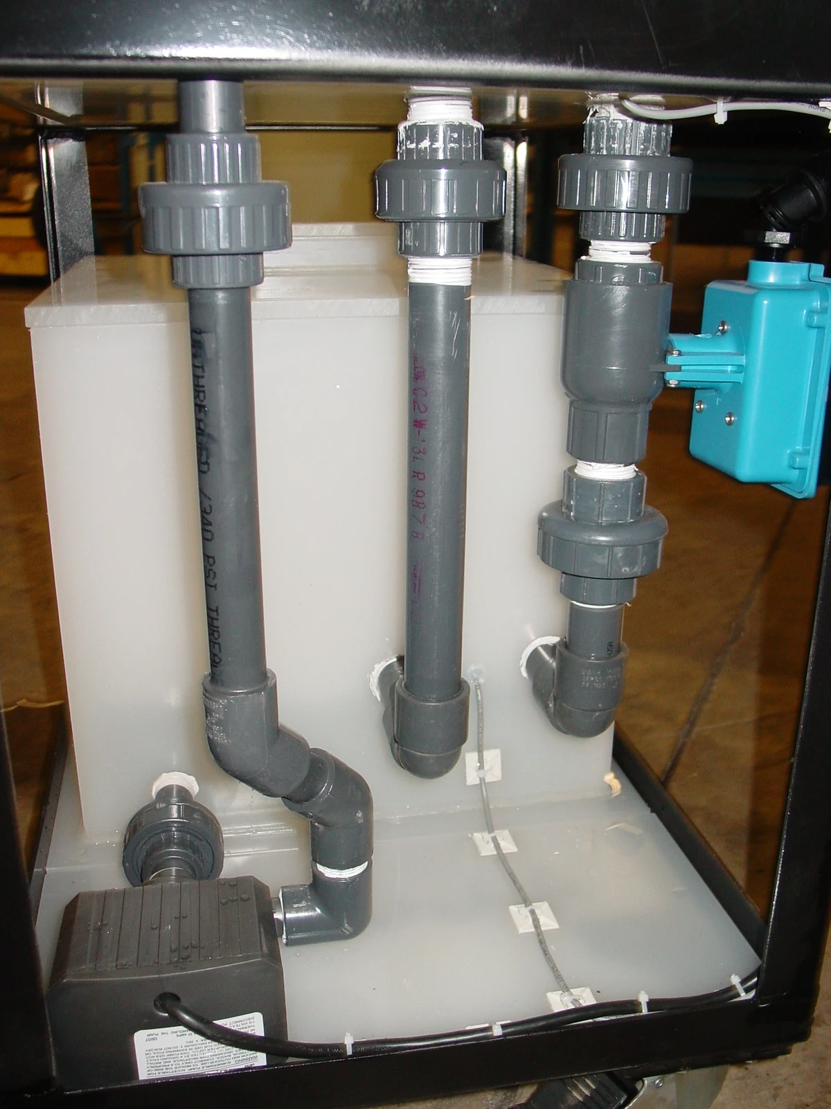
Layout of the immersion fill pump and associated plumbing used to move solution between the supply and test tanks.
Adjustable Float Switch Assembly
The adjustable float switch assembly signals the controls that the cabinet is full of solution during an immersion cycle. It is located inside the immersion zone and is adjustable in height.
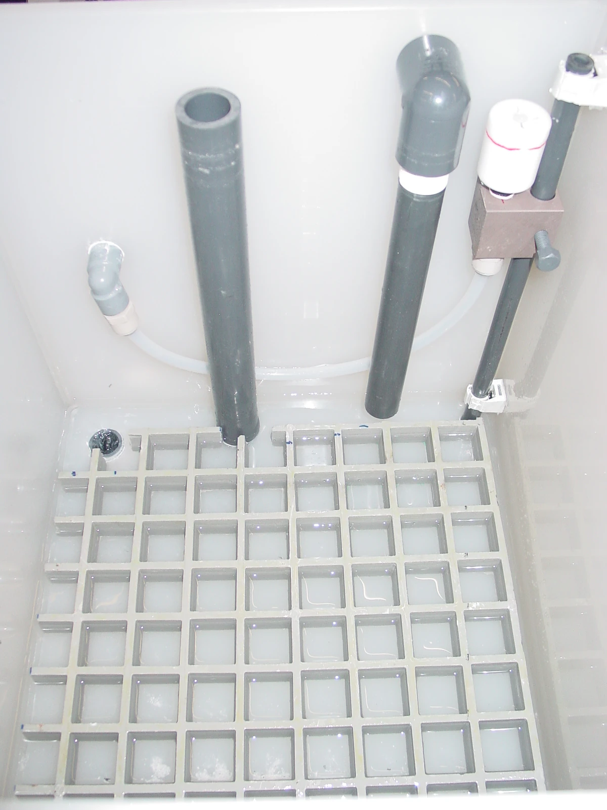
Internal view of the immersion zone featuring the adjustable float switch and testing grate.
Electronic Counter Control Panel
The front panel is equipped with electronic counters for Cycle Time, Immersion Time, and Cycle Count, along with start and stop controls for cyclic immersion testing.
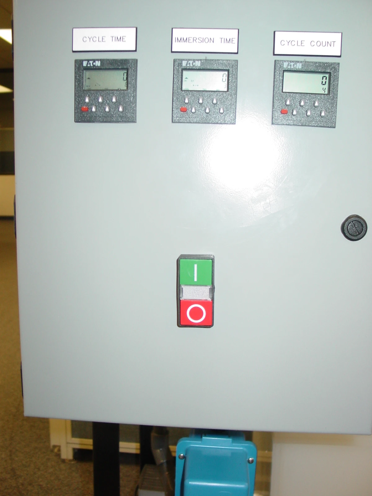
The main control panel equipped with programmable electronic counters for precise cyclic immersion testing.
Main Tank Drain
The main tank drain is used to remove used solution after testing is finished. The chamber drain must gravity feed to the floor drain and should not be directly connected into it.
The main tank drain (located under the cart at the back right) used to remove all used solution after testing is finished.
Full Key Features List
- Upper immersion test tank for cyclic exposure of test specimens
- Lower water supply tank for holding solution between cycles
- Immersion fill pump to move solution upward into the test tank
- Drain solenoid to allow solution to return during the cyclic process
- Adjustable float switch assembly to signal full solution level during immersion
- Overflow drain to prevent overfilling of the upper tank
- Electronic counters for Cycle Time, Immersion Time, and Cycle Count
- Manual DI water fill from an outer source for initial tank filling
- Main tank drain for complete drain-out after testing
- Built-to-order configuration based on required test-space and loading needs
Feature / Benefit Summary
| Feature | Benefit |
|---|---|
| Immersion Fill Pump | Moves solution from the lower reservoir into the upper test tank for immersion |
| Drain Solenoid | Allows solution to drain back during the cyclic process |
| Adjustable Float Switch Assembly | Signals when the immersion zone is full during the cycle |
| Electronic Counters | Controls cycle timing and repeatability from the front panel |
| Lower Water Supply Tank | Stores solution between immersion cycles |
| Main Tank Drain | Supports final solution removal and cleanout after testing |
Sizing
Cyclic Immersion Chambers are built to order. Final test-space dimensions, reservoir arrangement, and configuration depend on customer requirements and specimen loading needs.
Sizing depends on customer requirements. Final test-space layout, tank geometry, and working configuration should be matched to the customer’s cycle program and specimen size.
Installation & Facility Requirements
What Is Required for Chamber Installation
- Level floor
- Water connection
- Floor drain
- Customer-specified electric power
- 2 inch plastic (PVC) plumbing fittings for chamber drain to connect the chamber to the floor drain
Drain Connection
- The chamber drain must gravity feed to the floor drain
- The chamber is not designed to drain above floor level
- Do not directly connect into the floor drain
- Allow the chamber drain line to lay over the floor drain
Water Supply Requirements
- The chamber does not have an initial tank fill connection
- It must be manually filled with DI water from an outer source
- Pay close attention to the type of water used
Electrical Connection
- The chamber is wired for use with the customer-specified electrical supply
Access and Room Conditions
- The instrument must be accurately leveled
- Main access is from the front by the control panel
- The drain connection faces the back and plumbing is on the left side when facing the front
- Maintain at least 3 feet of open area in front for maintenance access
- The chamber should be installed in a climate-controlled room
- Recommended ambient temperature range is 20 to 25 °C (68 to 77 °F)
- Never allow the surrounding temperature to approach 0 °C (32 °F)
- The room should be properly ventilated with minimal drafts, air pollution, or dust
- Do not install the instrument in a corrosive or toxic environment
Improper installation will affect operation and compromise test integrity. Installation is strongly discouraged in a warehouse, boiler room, garage, factory floor, paint room, powder mixing room, or other areas with frequent dust, outside-door exposure, or widely varying humidity, air pressure, or temperature.
Photos
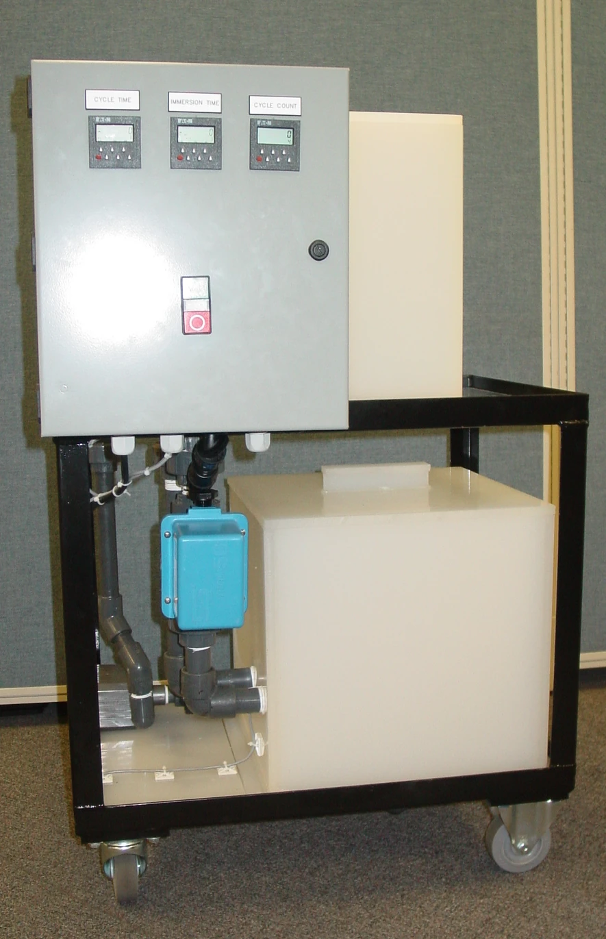
Front view of the unit highlighting the user interface and the integrated electronic counter system for automated cycling.
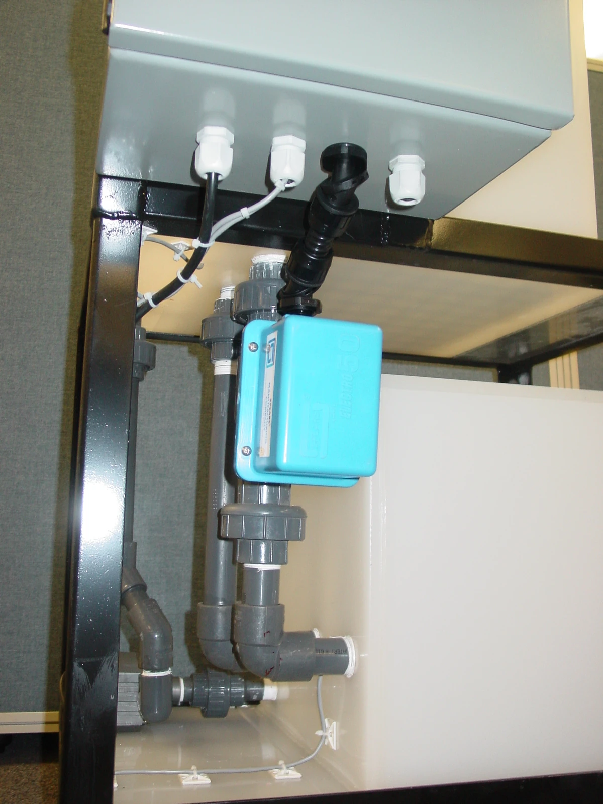
Detail of the immersion fill pump and drain solenoid plumbing located on the left side of the unit.
Side view highlighting the plumbing configuration and the lower 25-gallon solution reservoir.
FAQ
Is this a continuous immersion chamber?
No. This is a cyclic immersion chamber that repeatedly fills and drains the exposure tank as part of a programmed cycle.
How does the cyclic immersion process work?
The immersion fill pump moves solution from the lower supply tank to the upper test tank, and the chamber then returns the solution during the cyclic process.
Does the chamber have an automatic initial fill connection?
No. The chamber does not have an initial tank fill connection and must be manually filled with DI water from an outer source.
How is the immersion level controlled during the cycle?
An adjustable float switch assembly signals the controls when the exposure chamber is full during the immersion cycle.
Are standard chamber sizes available?
These chambers are built to order, so final test-space size, reservoir layout, and chamber configuration depend on customer requirements.
What kind of room does the chamber need?
The chamber should be installed in a climate-controlled room with a recommended ambient temperature of 20 to 25 °C, minimal drafts, and minimal dust or airborne contamination.