
MIXED FLOWING GAS (MFG) TEST CHAMBERS
Auto Technology Mixed Flowing Gas (MFG) chambers are designed for controlled atmospheric corrosion exposures using H2S, SO2, NO2, and Cl2. Systems are built to order for electronics, connector, and materials programs requiring controlled humidity, temperature, gas delivery, air exchange, and optional analyzer-based closed-loop concentration control.
Controlled Atmospheres
Designed for low-level pollutant gas environments with adjustable dilution airflow and air exchange.
Manual or Automated Control
Configure for manual setup or analyzer-based closed-loop concentration control with recipe management and logging.
Built to Size
Chambers are engineered to the required specimen loading, fixture layout, chamber volume, and facility constraints.
Tell us your target environment, chamber volume, analyzer requirements, and specimen configuration.
Overview
The Auto Technology Mixed Flowing Gas (MFG) chamber is designed to generate controlled low-level pollutant atmospheres used to evaluate corrosion susceptibility in electronic components, connectors, hardware, plated surfaces, and assemblies exposed to industrial or polluted environments.
The system supports controlled exposure to hydrogen sulfide (H2S), sulfur dioxide (SO2), nitrogen dioxide (NO2), and chlorine (Cl2), while regulating chamber temperature, relative humidity, airflow, and air exchange.
Engineering focus: MFG testing succeeds when gas generation, dilution airflow, air exchange, humidity, and temperature remain stable under real specimen loading. Chamber design, controls, and materials selection all directly affect data quality.
Mixed Flowing Gas Test Standards Supported
Auto Technology Mixed Flowing Gas (MFG) chambers are designed to reproduce controlled atmospheric corrosion environments used in electronics, connector, telecommunications, and industrial reliability testing programs. The system can be configured to support the mixed-gas environments defined by the following widely used test specifications.
- IEC 60068-2-60 — Environmental testing for electrotechnical products using mixed flowing gas atmospheres
- EIA-364-65 — Mixed flowing gas corrosion test procedure for electrical connectors and sockets
- Telcordia GR-1217 — Generic reliability requirements for telecommunications connectors and hardware
- ASTM B827 — Mixed flowing gas (MFG) corrosion testing practice
- ASTM B845 — Mixed flowing gas corrosion test for electrical contacts and connectors
- UL 294 Section 16 — Environmental corrosion testing for access control equipment
- Battelle Class I — Mild atmospheric corrosion environment
- Battelle Class II — Moderate atmospheric corrosion environment
- Battelle Class III — Harsh industrial corrosion environment
- Battelle Class IV — Severe corrosion environment
Flexible method implementation: Chambers can be configured to reproduce specific gas mixtures, concentrations, air exchange rates, and environmental conditions defined by these standards, or to replicate custom atmospheric corrosion environments required by customer test programs.
Environmental Control and Stability
The chamber maintains controlled temperature and humidity conditions required for atmospheric corrosion testing and long-duration mixed-gas exposures.
| Parameter | Specification |
|---|---|
| Temperature / RH setpoint range | 25°C to 35°C @ 25% to 75% RH |
| Temperature stability (guaranteed) | ±1.0°C under steady load conditions |
| Temperature stability (typical) | ±0.5°C |
| RH stability (guaranteed) | ±2.0% RH |
| RH stability (typical) | ±1.0% RH |
Probe protection: The temperature / humidity probe includes a chemical purge feature intended to improve probe longevity in corrosive mixed-gas environments.
Gas Delivery, Concentration Control, and Chamber Airflow
The chamber produces trace pollutant atmospheres through a controlled gas injection and dilution airflow system. Pollutant gases may be generated through permeation tubes or supplied from gas cylinders, then combined with clean dry air before entering the reaction chamber.
Supported Pollutant Gases
- Hydrogen Sulfide (H2S)
- Sulfur Dioxide (SO2)
- Nitrogen Dioxide (NO2)
- Chlorine (Cl2)
Typical Concentration Control Ranges
| Gas | Typical Analyzer-Based Range |
|---|---|
| H2S | 10 ppb – 1900 ppb |
| SO2 | 10 ppb – 1900 ppb |
| NO2 | 10 ppb – 1900 ppb |
| Cl2 | 10 ppb – 45 ppb |
Chlorine is highly reactive and low-level control may require longer stabilization time.
Airflow and Air Exchange
| Parameter | Specification |
|---|---|
| Total chamber airflow (12 ft³ typical chamber) | 5 – 56 LPM, adjustable |
| Total chamber airflow (42.5 ft³ typical chamber) | 20 – 200 LPM, adjustable |
| Air changes per hour | 2 – 10 |
Typical concentration-controlled operation: Many programs operate in the range of 5 – 10 air changes per hour to support stable concentration control.
Gas Generation System
| Method | Description |
|---|---|
| Permeation Tube System | (4) individual U-tubes, all running at the same temperature; each tube can hold multiple permeation tubes; gas flow variable for each tube |
| Gas Bottle Supply | Compressed gas cylinder supply supported where appropriate for the application |
Permeation Tube Temperature Control
| Parameter | Specification |
|---|---|
| Set point / control range | 20°C – 40°C |
| Typical operating set temperature | 30°C – 40°C |
| Stability | ±0.01°C |
| Uniformity | ±0.02°C |
Control System, Automation, and Analyzer Integration
The chamber controller is based on a Windows operating system running a National Instruments LabVIEW VI custom control software package on a panel-mounted PC. The system is designed to provide direct operational visibility, recipe execution, and data traceability.
Control System Features
- Panel-mount PC
- Recipe management
- Data logging
- Graphical system depiction for control and understanding
- Rack-mounted keyboard and trackpad
Analyzer Input / Control
The control system supports Ethernet communication and can accept input from up to 4 gas analyzers for real-time concentration control.
Manual and Automated Control
Chambers may be configured for manual gas setup and adjustment, or for automated analyzer-based closed-loop control, depending on the application and instrumentation package.
Remote Communication
A variety of information including alarms and operating status is available over Ethernet (site networking coordination may be required).
Chamber Construction and Wetted Materials
Chamber materials are selected for compatibility with mixed pollutant gas environments and for durability under long-duration exposure conditions.
| Component | Construction |
|---|---|
| Reaction chamber | Polypropylene and polycarbonate |
| Inside temperature chamber | Polypropylene |
| Exterior window | Double pane glass |
| Frame and external panels | Mild cold rolled steel, powder coated, Gray Ridge, Smooth |
| Chamber insulation | Styrofoam, encapsulated within chamber walls |
Materials in Contact with Process Gas
Main wetted materials include:
- Polypropylene
- Polycarbonate
- Polyethylene
- Nylon
- Some stainless and other materials where contact is unavoidable
Safety Interlocks, Warnings, and Fault Monitoring
The chamber includes monitoring and interlock functions intended to support safe operation and facility integration when handling reactive gases.
Reaction Chamber Safety Interlock
Delta P sensor in reaction chamber exhaust detects backpressure in the vent system.
Warnings
- Out of temperature range
- Out of RH range
- Controller warning
- Saturator warning
- MFC warning
Faults
- Water leak detect fault
- U tube bath fault
- Controller fault
- EMO
- DeltaP fault
Safety certification note: Designed to meet SEMI S2, F47. NRTL Field Inspection Label optional at additional cost.
Illumination
A small light inside the reaction chamber area.
Chamber Sizes and Configurations
Auto Technology MFG chambers are built to order based on specimen loading, internal fixture requirements, gas control strategy, airflow requirements, and available facility space.
The dimensions below represent common reference configurations used for design and gas control calculations. Actual usable volume may be affected by hangers, shelves, mixing fans, and other internal components.
Reference Reaction Chamber Test Space Dimensions
| Configuration | Dimensions | Nominal Volume |
|---|---|---|
| Reference Configuration 1 | 30" W × 36" H × 16" D | 10 ft³ |
| Reference Configuration 2 | 36" W × 48" H × 36" D | 36 ft³ |
Reference System External Dimensions
| Configuration | External Dimensions |
|---|---|
| Reference Configuration 1 | 82" W × 85" H × 30" D |
| Reference Configuration 2 | 88" W × 100" H × 52" D |
Custom layouts supported: Chamber dimensions and internal layouts can be adjusted for specimen racks, shelves, mixing fans, wiring ports, custom fixtures, and other application-specific hardware.
Facility, Utility, and Installation Requirements
Utility Requirements
| Requirement | Specification |
|---|---|
| Clean Dry Air (CDA) | 3 – 5 scfm, 80 – 150 psi, -60°C dew point, oil free, per EIA Standard EIA-364-65B |
| Humidifier water | Max 1 L/hour, filtered city water |
| Chamber power | 208 / 220 / 240 VAC ±10% 60 Hz, or 200 VAC ±10% 50 Hz, 1 ph, FLA 30A |
| Exhaust | 200 CFM @ 2" water |
Clearance Requirements
- 36" on left side
- 36" on right side
- 48" on front side
- No clearance required on rear side
Environmental Conditions for Chamber Location
| Parameter | Customer Site Requirement |
|---|---|
| Ambient temperature | 20 ± 2.0°C |
| Maximum rate of change | 1°C / 30 minutes |
| Humidity | 35% – 65% |
| Cleanliness | No heavy dust |
| Acoustic noise | No spec |
Verification and Coupon Monitoring
Many MFG programs use coupon monitoring to verify environmental corrosivity and confirm that the chamber is maintaining the intended exposure severity. Chamber layouts can be configured to support coupon placement alongside test specimens.
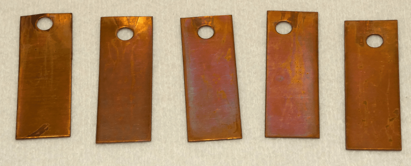
Copper mass gain coupon monitoring: High-purity copper mass gain coupons are utilized to monitor environmental corrosivity within the reaction chamber. By exposing these precision samples to controlled concentrations of H2S, SO2, NO2, and Cl2, labs can accurately measure atmospheric corrosion rates and validate test stability.
System Photos and Example Configurations
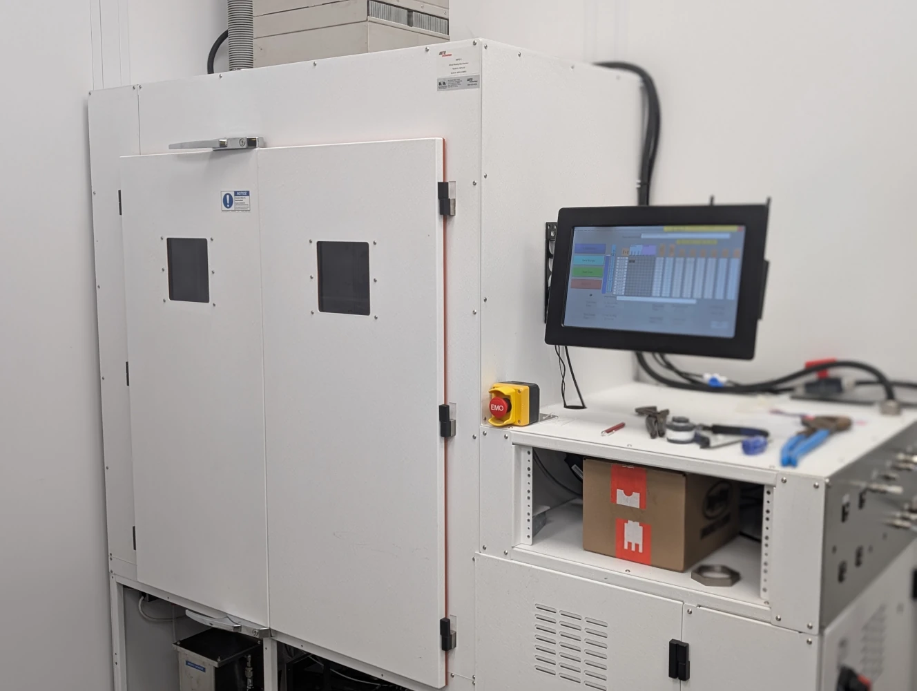
A custom 10 cubic foot MFG chamber offers a compact yet powerful solution for precision corrosion testing.
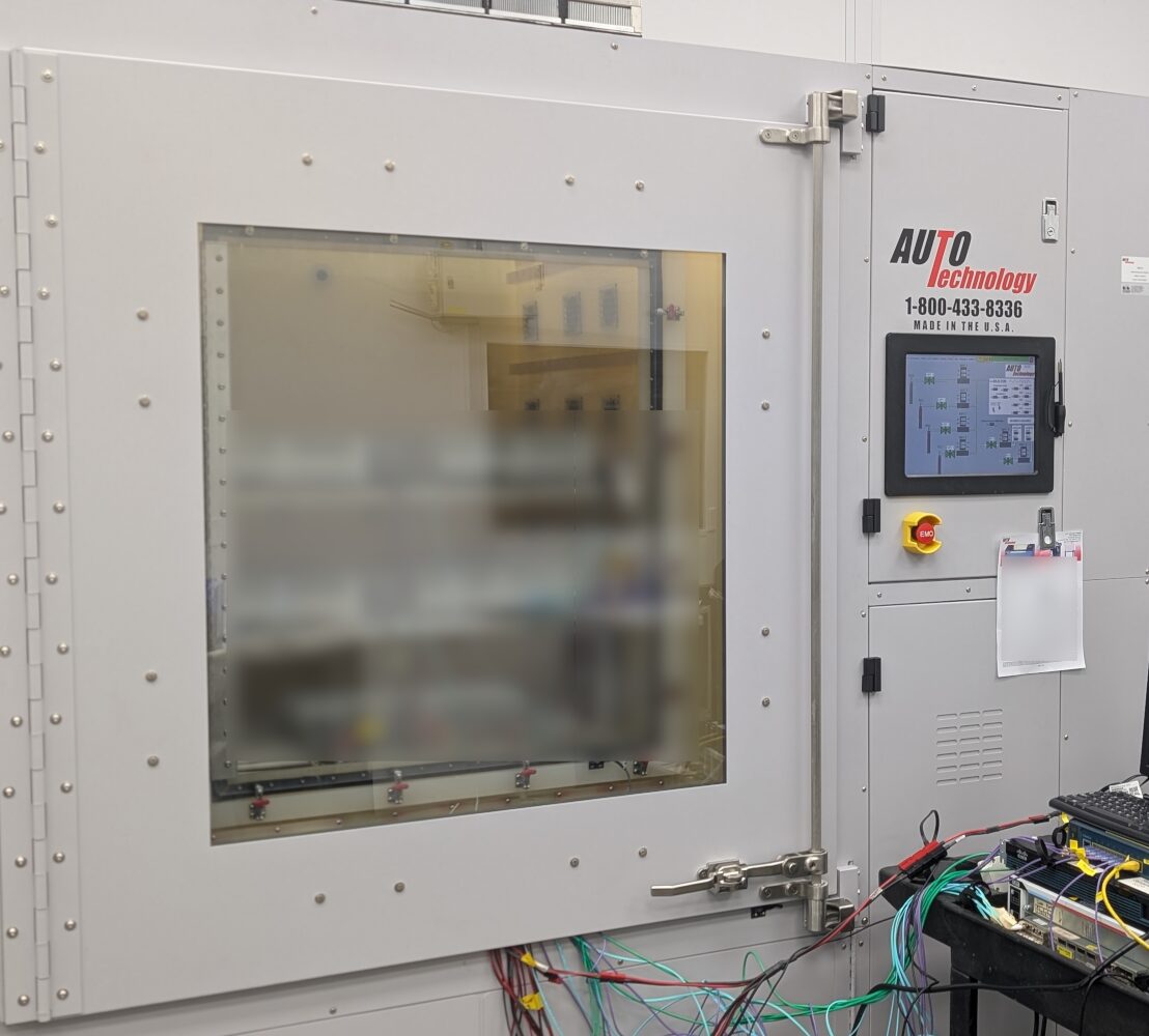
This custom-configured 36 cubic foot MFG chamber is designed to accommodate complex testing requirements, including "hot" or live-wired electronics.

Walk-in MFG chamber engineered for large assemblies and higher-throughput test programs.
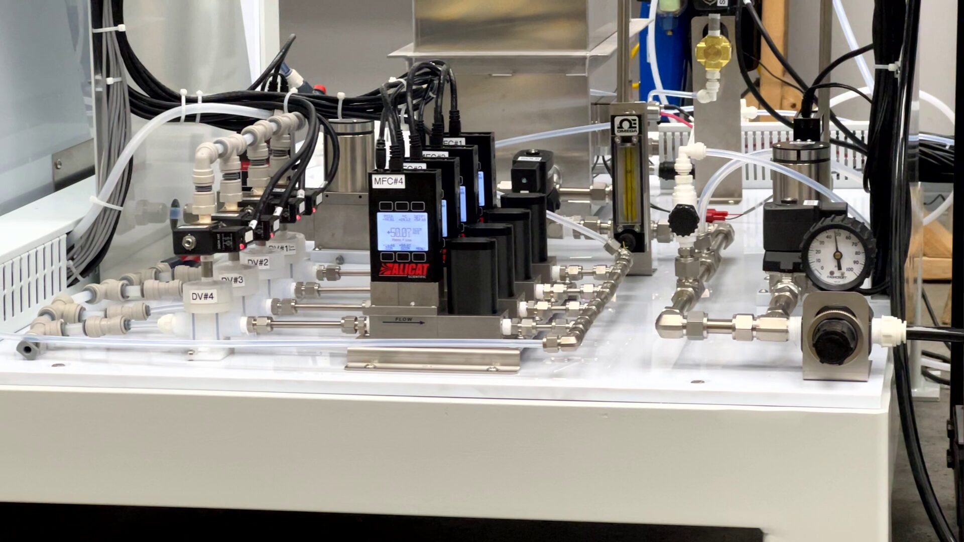
Flow control and instrumentation used to manage pollutant gas delivery, dilution airflow, and chamber conditions.

Chamber configurations may be scaled for electronics, connector, and larger assembly programs.
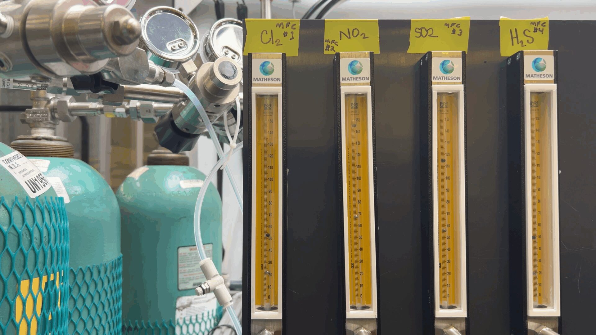
Gas delivery hardware introduces reactive gases into a controlled dilution airflow stream prior to chamber entry.
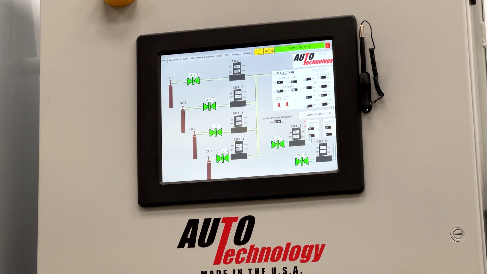
Control interface provides recipe management, monitoring, logging, and traceability.
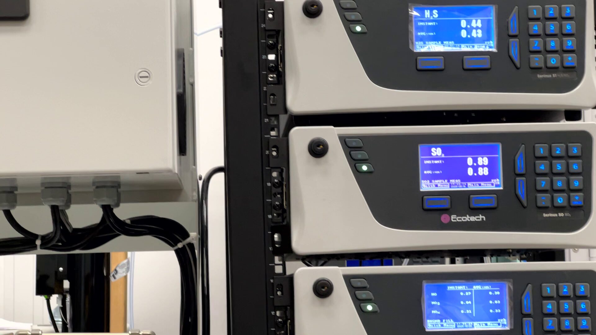
Analyzer integration supports real-time monitoring and closed-loop concentration control where specified.
Watch: A Mixed Flowing Gas (MFG) Chamber Custom Built for a Global Test Lab
Mixed Flowing Gas Test Services
Not every program requires an in-house MFG chamber immediately. Auto Technology also supports mixed flowing gas test services for customers who need atmospheric corrosion testing, method development, correlation work, qualification testing, or ongoing outsourced exposure programs.
These services are useful for engineering teams that want to validate a product, investigate field failures, compare materials or platings, or establish an exposure program before purchasing capital equipment.
Typical Test Service Applications
- IEC 60068-2-60 mixed flowing gas testing
- EIA-364-65 connector corrosion testing
- Battelle Class I–IV environmental exposures
- Coupon-based corrosivity verification
- Failure analysis and environmental replication
- Method development and chamber correlation
When Test Services Make Sense
- Early-stage product validation
- Low annual test volume
- Need for third-party verification
- Bridge testing before equipment purchase
- Programs requiring immediate test capacity
Need testing instead of equipment? We can help define the appropriate gas environment, duration, coupon monitoring approach, and sample configuration for your program.
Tell us your standard, gas mix, exposure duration, coupon requirements, and sample quantity.
Frequently Asked Questions
Can the chamber be configured for manual setup or automated analyzer control?
Yes. The system may be configured for manual gas setup and adjustment, or with analyzer input for automated closed-loop concentration control. Up to four gas analyzers can be integrated through Ethernet communication.
What gases are supported?
The chamber supports H2S, SO2, NO2, and Cl2. Concentration ranges depend on the analyzer and gas generation configuration.
Are chambers limited to the reference 10 ft³ / 36 ft³ sizes?
No. Those are common reference configurations. Chambers are built to order around the required volume, fixture arrangement, airflow requirements, and facility constraints.
Can coupon monitoring be incorporated into the chamber?
Yes. Chambers can be configured to support coupon exposure and environmental verification programs such as copper mass gain monitoring.
What facility systems are required?
The system requires clean dry air, humidifier water, electrical power, and exhaust ventilation meeting the specified utility requirements. Stable room conditions and appropriate exhaust design are important for proper operation.