
INSTALLING YOUR CORROSION CHAMBER

How to Design a Reliable, Standards-Compliant Testing Environment
Corrosion chambers are precision laboratory instruments — not simple appliances. The room they live in directly affects performance, repeatability, and long-term reliability.
Planning guideline: The requirements below provide general facility and installation guidance. Chamber configurations and facilities vary, and Auto Technology can work with customers to support necessary site-specific modifications.
Proper facility planning ensures:
- Accurate, repeatable test results
- Stable chamber performance
- Reduced downtime
- Long equipment life
- Compliance with ASTM, ISO, and OEM standards
Installation
Follow the manual for complete instructions, and contact Auto Technology about alternative arrangements.
- Location: Final installation area on a level floor, with the drain, power, DI water, compressed air, and exterior vent or scrubber location within 10 feet. Leave 24 inches in front and behind and on the side of a side-mounted vent; allow 36 inches with a recirculating scrubber.1
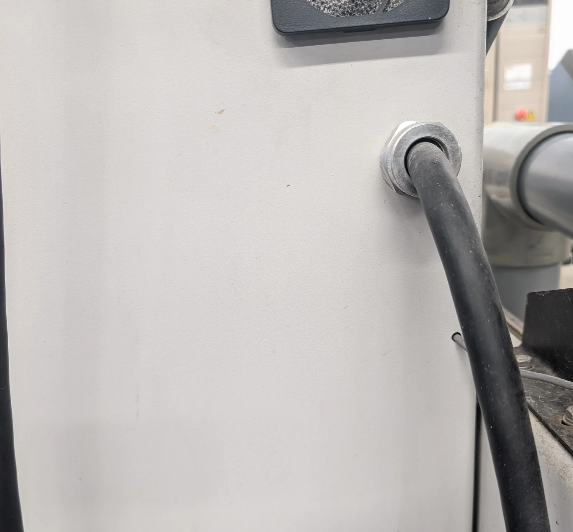
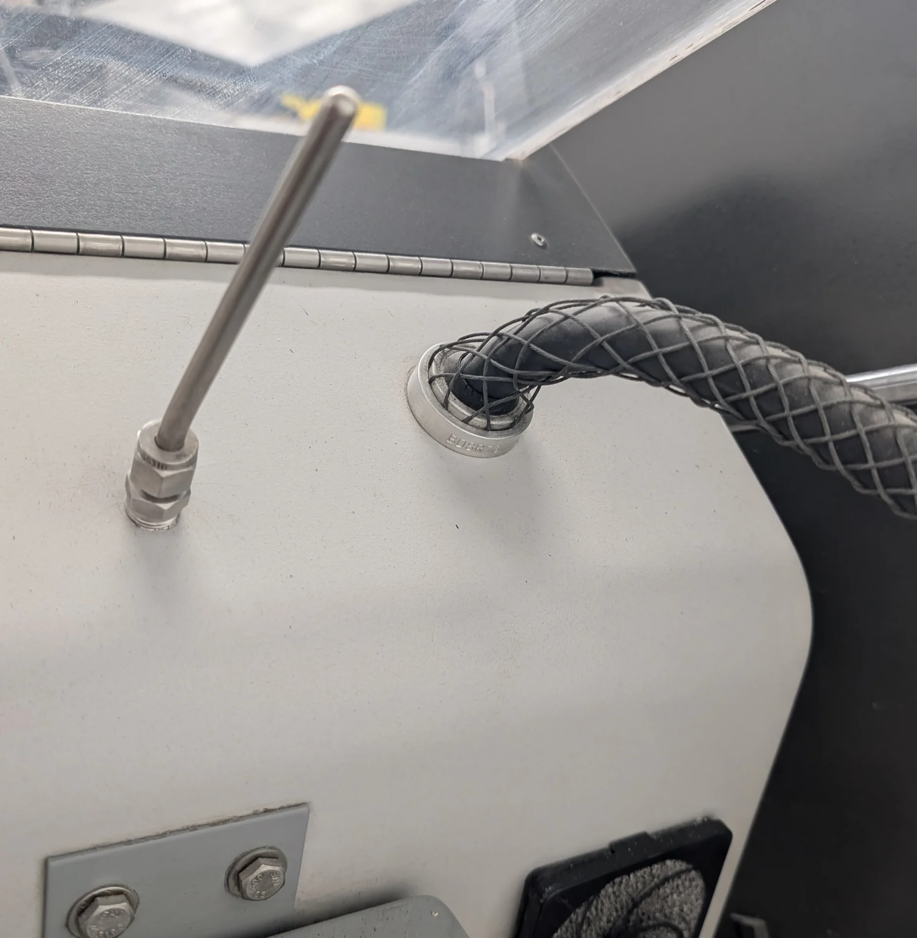
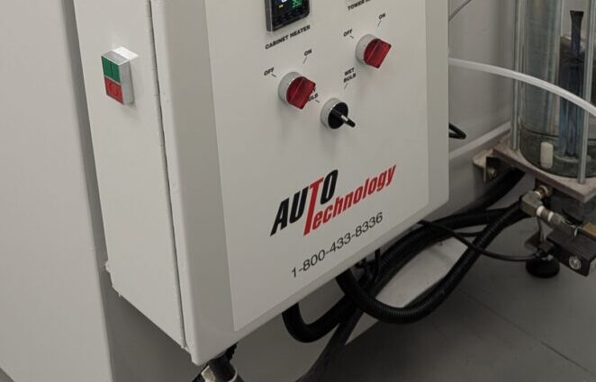
- Electrical: Power fully installed and connected through a nearby, clearly visible, properly rated and sized fused disconnect. Wiring, conduit, and grounding must meet local codes.
- Drain: Open, floor-level gravity drain that accepts a 1-inch drain hose. If no floor drain is available, contact Auto Technology before installation.
- Water: ASTM D1193 Type IV DI water at 20–40 psi, plus city water when required by the chamber or scrubber.
- Air: Continuous, clean, dry, oil-free compressed air at 65–85 psi.
- Exhaust: Exterior ventilation or a properly selected scrubber. A scrubber discharging indoors adds humidity and heat to the room.2
If Auto Technology Is Installing Your Chamber
Before we arrive: Review the checklist above and make sure power is connected to the chamber, all required utilities are available, and the ventilation plan is confirmed. If the leveling feet have not been installed, have a pallet jack available.
During installation, we will: Check for shipping issues, install or adjust the feet, level the chamber, set up towers and internal components, connect air and water tubing, help route the drain, and guide the first startup.
You will still need to complete: Facility electrical work and final exterior vent piping. We can provide guidance.
1 Where required by the manual, keep the chamber supported on the forks until all leveling feet are installed.
2 If Auto Technology is installing the chamber, complete the final exterior vent connection after we level it.
Facility note: Because the chamber uses pressurized air and water, make sure your facility is prepared to manage a leak.
Electrical
A dedicated, properly protected electrical supply is required for safe and stable operation.
- Dedicated circuit per chamber (no shared loads)
- Nearby, clearly visible, properly rated and sized fused disconnect
- Proper grounding and bonding
- Correct voltage and phase per model
- Surge protection recommended for sensitive control electronics
Tip: Avoid extension cords or temporary wiring — voltage drop and noise can cause controller faults.
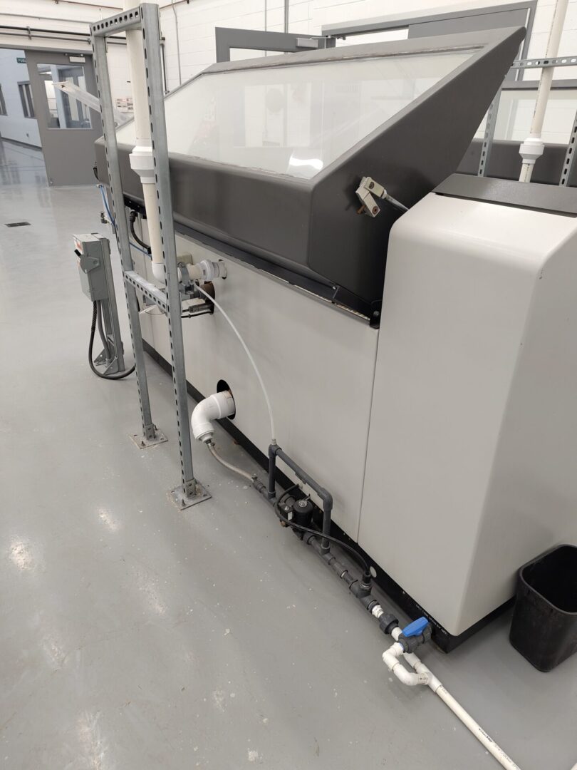
Plumbing & Utilities
Reliable water and air supply directly impact test repeatability, uptime, and chamber longevity.
- Water: ASTM D1193 Type IV (Conductivity < 5 µS/cm); 20–40 psi
- Scrubber water: City-water connection required for a non-recirculating scrubber
- Air: Continuous 65–85 psi (Clean, Dry, Oil-Free)
- Connections: Strain relief required on all hard connections
During an Auto Technology installation: The technician can connect the chamber tubing for DI water and compressed air and help route the chamber drain tubing to the customer's open floor drain. The facility supplies and drain must be available at the chamber before the visit.
Best practice: When possible, supply the corrosion lab with a dedicated DI water system and a dedicated, continuous-duty-rated, oil-free air compressor (or dedicated branch with clearly labeled, lockable isolation valves). Utility outages and maintenance work are a recurring cause of avoidable downtime and equipment damage — especially when facilities teams service shared systems without realizing the corrosion lab is attached.
Critical warning: If compressed air is interrupted while the chamber continues running,
liquid can migrate into the air circuits.
This is one of the most costly failure modes — it can require replacement of multiple air-path components.
Prevent it: Whenever the utilities are shut down, serviced, or isolated, the corrosion chamber must be
shut down.

M Series: DI water and compressed air supply connections.

C, A & X Series: DI water, air, and custom 3rd connection.
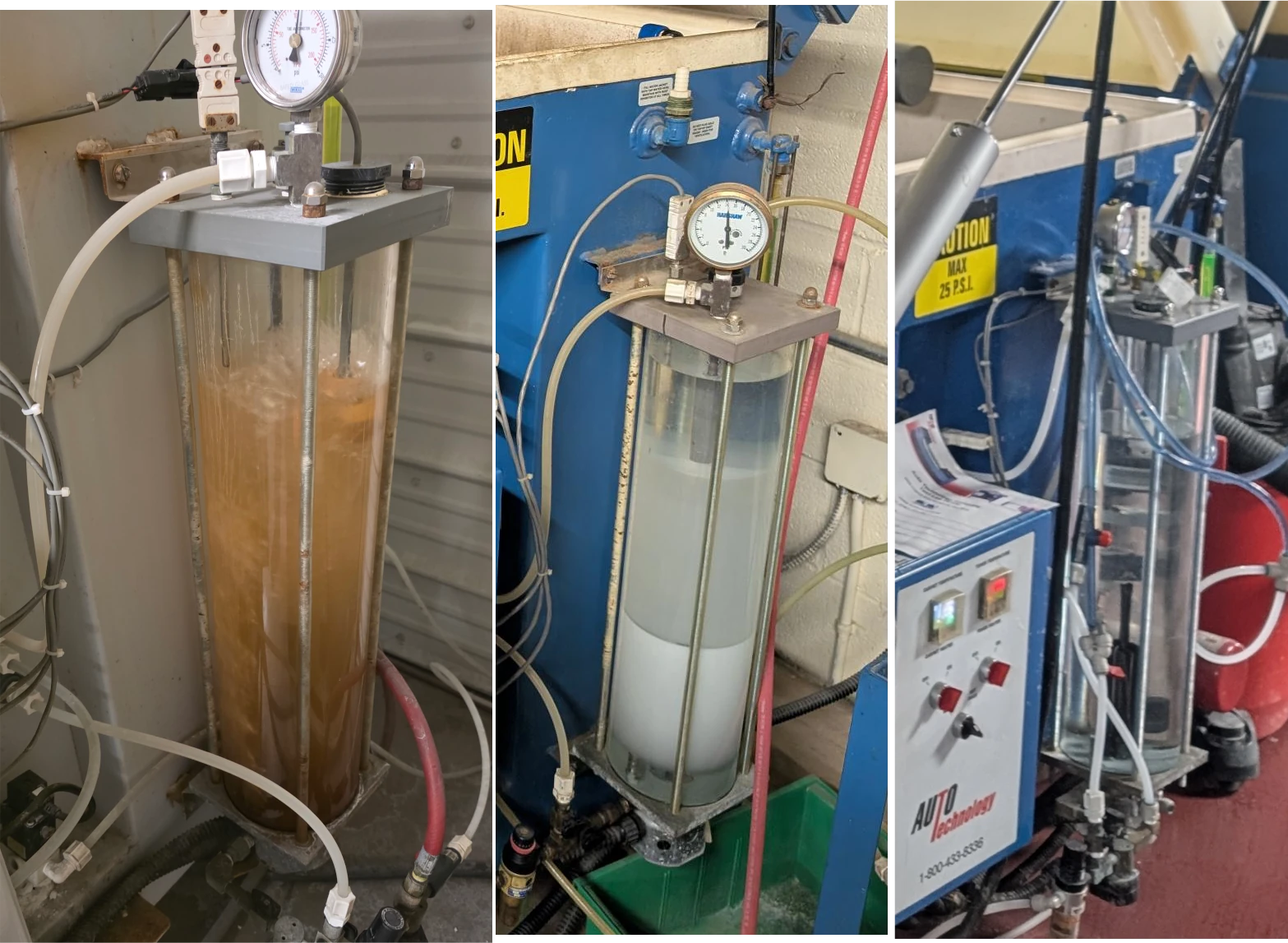
Drainage, Filtration & Control Examples


Ventilation & Exhaust
Salt fog is highly corrosive. Proper exhaust protects both your building and your test data. Every chamber must be connected to either a dedicated exterior ventilation system or a properly selected scrubber.
- Exterior ventilation: Route the chamber exhaust directly outdoors using corrosion-resistant PVC ducting.
- Scrubber: When a scrubber is used without exterior ventilation, the scrubbed exhaust—including its humidity—discharges into the room.
- The facility HVAC must be able to manage the added moisture and heat from an indoor-discharging scrubber.
- Never tie chamber exhaust into shared lab ductwork or a building plenum.
- Avoid sharp bends or restrictions that cause backpressure.
- Exterior vent runs of more than 15 feet require special equipment.
Required: Do not operate the chamber without either an exterior ventilation connection or a properly selected scrubber. Contact Auto Technology before installation if exterior ventilation is not available.
Tip: Ensure proper vent pitch to minimize condensation.
Installation sequence: Position and properly level the chamber before completing the final exterior ventilation or scrubber connection. When exterior ventilation is used with an Auto Technology installation, the customer should finalize the piping from the chamber vent to the exterior after the chamber has been installed and leveled so the connection aligns correctly. Auto Technology technicians generally do not install the final exterior vent piping, but they can provide layout and connection guidance.
Tip: In pressure-controlled lab environments (positive or negative), drainage and exhaust systems must include proper traps or isolation devices to prevent pressure-induced backflow or siphoning.

Balancing & control: Manual damper for airflow tuning and system balancing.
Venting Hardware Examples


Room Environmental Conditions Dictated By Common Standards
- Temperature: 20–25°C (68–77°F)
- Humidity: 45 ±10% RH
- Non-condensing environment recommended
- Avoid high humidity and temperature swings
Intake Air Quality (Purge Cycle, if equipped): The chamber's purge blower uses ambient room air. Ensure the room is free of dust, paint fumes, and chemical vapors. If the room air is contaminated, those contaminants can be blown directly onto your test specimens during the dry cycle, potentially invalidating results.
Tip: Treat the room like a lab, not a warehouse.
Space Planning & Layout
- Locate the drain, electrical service, DI water, compressed air, and ventilation connection within 10 feet of the chamber
- Leave at least 24 inches of open space in front of and behind the chamber
- For an M Series chamber with a side vent, leave at least 24 inches on the vent side
- Provide at least 36 inches of clearance when a recirculating scrubber is installed
- Door swing and lid clearance
- Space for solution mixing and sample handling
- Bench/prep area nearby
- Storage for salt, DI water, spare parts
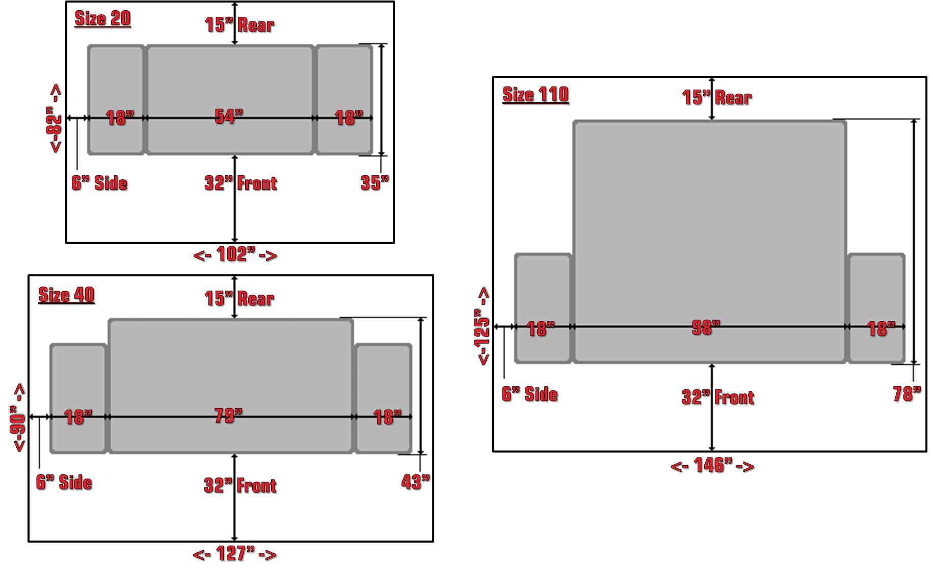
M, A, & X Series floor-plan guidance for chamber placement, service clearances, and room layout.
Floor & Structural Requirements
Chambers, solution tanks, and water jackets are heavy when filled. Plan for a stable surface, reliable open drainage, and an installation location that won’t put other equipment at risk.
- Flat, level concrete floor recommended (leveling is required for proper internal open drainage)
- Verify floor loading capacity for filled chamber + tanks
- Open, floor-level gravity drain capable of handling the necessary wastewater and accommodating a 1-inch drain hose
- Chemical-resistant coatings preferred
- Avoid carpet, tile, wood, or porous surfaces
Drainage Physics: Chamber drains are gravity-fed. The drain line must pitch downhill continuously. Do not hard-pipe the chamber drain directly to a sewer line. An open site drain or air gap is normally required to prevent siphoning and sewer gas backflow. If an open floor drain is unavailable, contact Auto Technology before installation to determine whether an alternative drainage arrangement can be supported.
Location warning: Do not install corrosion chambers near, above, or below sensitive equipment areas such as server rooms, electrical rooms, clean rooms, or electronics/controls cabinets. Salt fog residue, condensate, and accidental leaks can migrate through floors, drains, or ventilation pathways and cause costly damage.
Leak preparedness: Because pressurized air and water are connected to the chamber, the customer must ensure the facility is properly prepared to manage a leak.


Chemical Handling & Storage
- Dedicated chemical storage area
- Sealed containers and clear labeling
- Secondary containment where required
- Mixing station with sink and rinse capability
Heat Rejection & HVAC Load
- Confirm HVAC capacity for heat load
- Avoid small enclosed rooms without airflow
- Maintain consistent ambient conditions
- Consider dedicated supplemental cooling for multiple chambers
Safety & Compliance
- Eye wash station recommended
- PPE storage
- Non-slip floors
- Adequate lighting
- Emergency access paths
- Compliance with local electrical and mechanical codes
- Facility provisions and response procedures appropriate for a potential pressurized-air or water leak
Planning for Growth
- Additional chambers
- Extra utilities and isolation valves
- Future exhaust capacity
- Extra floor drain capacity
It is far easier to oversize utilities now than retrofit later.