
M SERIES STEEL SALT FOG & HUMIDITY CHAMBERS

Auto Technology M Series salt spray chambers and salt fog chambers use a traditional steel, water-jacket-heated design for steady-state corrosion testing. Standard configurations are intended primarily for ASTM B117, ISO 9227, MIL-STD-810 Method 509.7, and related salt spray and salt fog procedures. Optional configurations are available for CASS, ASTM G85, ASTM D2247 humidity testing, and SO2-based procedures.

Important: The external 55-gallon solution tank supplied with the M Series is not pictured here.
Traditional Steel Construction
Steel chamber with indirect water-jacket heating and a corrosion-resistant interior lining.
Standard Salt Fog Configuration
Conditioned atomizing air, fog dispersion tower, external solution reservoir, specimen supports, and collection hardware.
U.S. Manufacturing & Service
Manufactured in Ohio with replacement parts, calibration, service, consumables, and technical support available from Auto Technology.
Provide the test standard and revision, chamber size, electrical service, utilities, specimen dimensions, loading requirements, and any required option packages.
M Series Steel Salt Spray & Salt Fog Chambers
Auto Technology M Series chambers are steel salt spray and salt fog test chambers used for accelerated corrosion testing of coatings, plated parts, passivated stainless steel, conversion-coated aluminum, fasteners, connectors, hardware, and assemblies. The standard chamber uses indirect water-jacket heating, conditioned compressed air, atomized test solution, fog dispersion towers, an external solution reservoir, and corrosion-resistant specimen supports.
Standard M Series configurations are intended primarily for ASTM B117 salt spray testing, ISO 9227 NSS / AASS, MIL-STD-810 Method 509.7, and related steady-state salt fog methods. Optional configurations support ASTM B368 CASS, selected ASTM G85 procedures, ASTM D2247 humidity testing, DIN 50018 / SO2 procedures, and other specified methods.
Traditional Steel Chamber Construction
ASTM B117 and related salt spray procedures have been run for decades in steel chambers using indirect water-jacket heating. Laboratories replacing existing equipment or maintaining long-running qualification programs may specify a similar chamber architecture to maintain consistency with established equipment, procedures, and historical test programs.
- Indirect water-jacket cabinet heating
- Bubble-tower-conditioned atomizing air
- Fog dispersion towers and atomizing nozzles
- Angled cover and chamber drainage geometry
- External solution reservoir with air agitation
Chamber Design
Primary Design Elements
- Angled clear cover with anti-drip slope to prevent solution from dripping onto specimens
- Water-jacket heating system for indirect, stable cabinet temperature control consistent with ASTM B117
- Multi-function bubble tower for atomizing air conditioning and fog consistency
- Wet bulb and exposed RTD measurement for monitoring chamber conditions and estimating humidity
- High-precision fog towers and nozzles designed to prevent direct spray impingement on specimens while generating uniform fog distribution
- 55-gallon solution tank with air agitation for consistent solution mixing and delivery
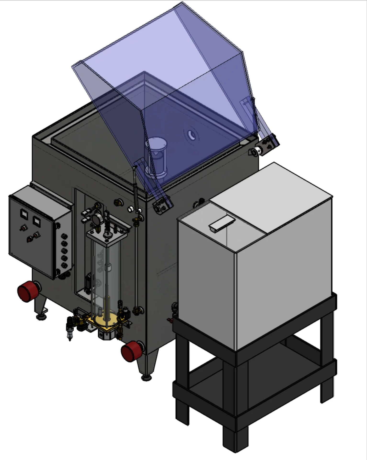
The M Series Design
The M Series uses indirect cabinet heating, conditioned atomizing air, controlled fog generation, and a 55-gallon agitated solution tank for cabinet temperature control, atomizing-air conditioning, fog generation, and test-solution supply.
Humidity Configuration
The M Series can use DI water in the solution tank for water-fog humidity exposure. Formal humidity methods such as ASTM D2247 require the appropriate humidity and drain configuration to be specified when the chamber is ordered.
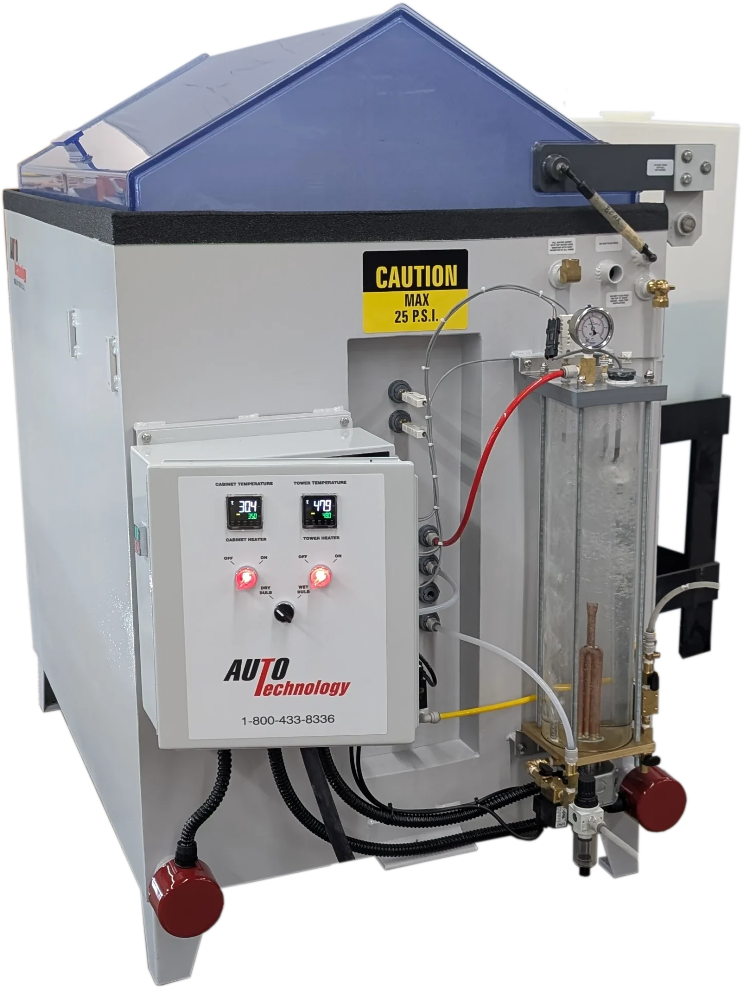
Salt Spray Standards & Chamber Configuration
Standards Supported in the Standard Configuration
The M Series is configured around the applicable salt spray, salt fog, humidity, or corrosion test specification. The methods below are separated into procedures supported by the standard chamber configuration and procedures that require additional chamber options or construction changes.
- ASTM B117 — Salt Spray (Salt Fog) Corrosion Test / Standard Practice for Operating Salt Spray Apparatus
- ISO 9227 — NSS / AASS salt spray testing
- ASTM G85 A1 — Acetic acid salt fog
- GB/T 10125 — NSS / AASS salt spray methods
- JIS Z 2371 — Neutral salt spray testing
- ISO 7253 — Neutral salt spray testing
- IEC 60068-2-11 — Salt mist environmental testing
- EIA-364-31 — Electrical connector corrosion testing
- ISO 9022-4 — Environmental testing for optical equipment
- MIL-STD-810 Method 509.7 — Salt fog environmental testing
- MIL-STD-202 Method 101
- MIL-STD-883 Method 1009
- MIL-STD-750 Method 1046.3
- MIL-STD-331 C3
- EN 13523-8
- BMW AA-0213
- Jaguar TPJLR.52.252 / TPJLR.52.253
- VW 80000 K-06 / K-07
Standards Requiring Additional Configuration
- ASTM B368 — Copper Accelerated Acetic Acid Salt Spray (CASS)
- ASTM G85 A2 — Supported with required options
- ASTM G85 A3 — Supported with required options
- ASTM G85 A4 — Supported with required options
- ASTM D2247 — Constant high-humidity exposure with required options
- ASTM D1735 — Water fog exposure using salt spray-style apparatus with required options
- ISO 6270-3 — Humidity / condensation exposure with required options
- DIN 50018 — SO2 condensation corrosion testing with required options
- JIS H 8502 — Salt spray and CASS / SO2 variants with required options
- Nissan MES-M0007 5.22
- Toyota TSH1552G
- MIL-DTL-5541 — Common conversion-coating specification referencing ASTM B117 salt spray
Configuration note: Not every listed procedure runs in the standard M Series configuration. Depending on the test method, required equipment may include SO2 dosing, high-temperature construction, humidity piping, a wet-bottom drain, or cyclic controls.
Configuration Requirements by Standard
| Standard / Method | Required Add-Ons | Recommended Add-Ons |
|---|---|---|
| ASTM B368 / ISO 9227 CASS / JIS H 8502 CASS / GB/T 10125 CASS | High Temperature Package | — |
| ASTM G85 A2 | High Temperature Package + Cyclic Controls + Wet Bottom Capability for most testing | ASTM G85 A2 includes a dry-bottom exception for 2000-series aluminum alloys and paint coatings requiring a less aggressive environment. |
| ASTM G85 A3 | Cyclic Controls + Wet Bottom Capability | ASTM G85 A3 states that wet-bottom operation is necessary. |
| ASTM G85 A4 / DIN 50018 / JIS H 8502 SO2 Variants / Related SO2 Methods | SO2 Package | Cyclic Controls |
| ASTM D2247 / ASTM D1735 / ISO 6270-3 | Humidity Pipe Assembly + Wet Bottom Drain Assembly | Operator planning for humidity-specific operation |
Humidity configuration: DI water may be used in the solution tank for water-fog humidity exposure. Formal procedures such as ASTM D2247, ASTM D1735, or ISO 6270-3 should be identified when ordering so the required humidity piping, wet-bottom drain, and operating configuration can be supplied.
Sizes & Configurations
Select M Series chamber size based on maximum specimen dimensions, specimen quantity, required spacing, support hardware, operator access, and available installation footprint. Standard-, low-, and high-profile configurations are listed separately below.
Size selection: Increasing chamber size changes exposure-zone dimensions, specimen capacity, solution requirements, installed footprint, and service clearance. Profile selection primarily changes usable height and operator reach.
Profile Selection Guidance
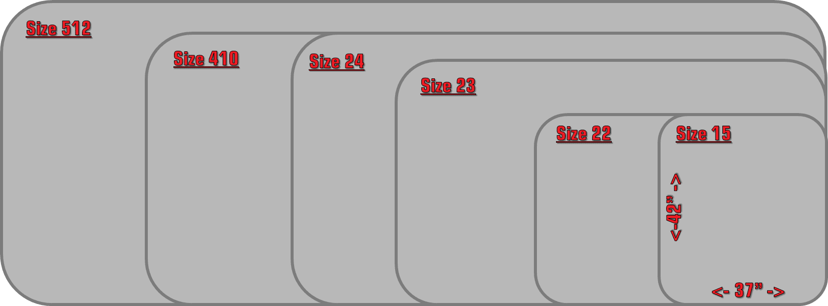
Compare footprint dimensions across the M-Series line, ranging from the compact Size 15 (37" x 42") to the high-capacity Size 512.
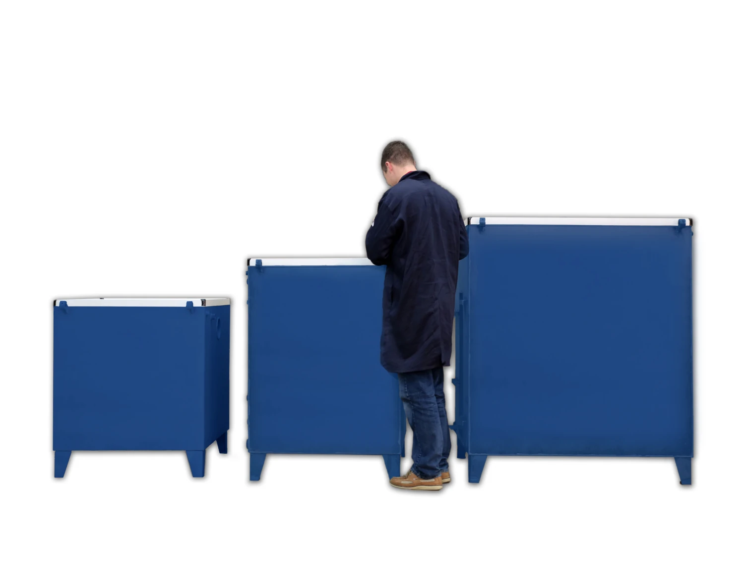
Use low profile for small parts and coupons, standard depth for traditional loading, and high / deep profile for extra-large parts.
Standard Profile Models
Standard Profile Model Chart
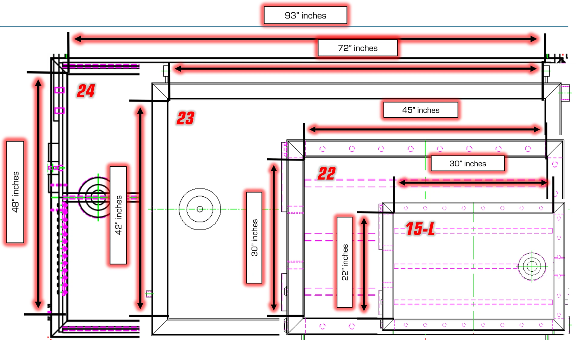
Internal capacity schematic comparing the length and width dimensions of the actual exposure zone across M Series salt fog corrosion chambers. This diagram provides direct visualization of the testing envelope available for specimen placement in Models 24, 23, 22, and 15-L.
| Model | Part Number | Internal Volume | Exposure Zone (in) | Exposure Zone (cm) | Chamber Only (in) | Chamber + Tank (in) |
|---|---|---|---|---|---|---|
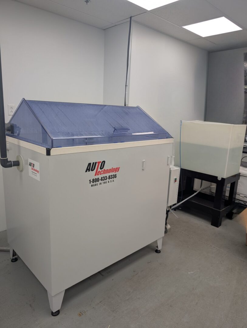
 15-L
15-LView Photo ↗ |
C100015-L | 12 ft³ / 339 L | 22 × 30 × 29 | 57 × 76 × 75 | 37 × 42 × 52 | 73 × 42 × 52 |
| 22 | C100022 | 30 ft³ / 849 L | 45 × 30 × 38 | 116 × 76 × 98 | 64 × 42 × 63 | 100 × 42 × 63 |
| 23 | C100023 | 68 ft³ / 1925 L | 72 × 42 × 38 | 183 × 107 × 98 | 95 × 54 × 67 | 131 × 54 × 67 |
| 24 | C100024 | 100 ft³ / 2831 L | 93 × 48 × 38 | 237 × 122 × 98 | 118 × 60 × 67 | 154 × 60 × 67 |
| 410 | C100041 | 130 ft³ / 3681 L | 120 × 48 × 38 | 305 × 122 × 98 | 150 × 60 × 67 | 186 × 60 × 67 |
| 512 | C100052 | 194 ft³ / 5493 L | 144 × 60 × 38 | 366 × 153 × 98 | 182 × 67 × 70 | 218 × 67 × 70 |
View Low Profile Model Chart
| Model | Part Number | Internal Volume | Exposure Zone (in) | Exposure Zone (cm) | Chamber Only (in) | Chamber + Tank (in) |
|---|---|---|---|---|---|---|
|
15-L View Photo ↗ |
C100015-L | 12 ft³ / 339 L | 22.65 × 30.27 × 29.64 | 57.5 × 76.9 × 75.3 | 37 × 42 × 52 | 73 × 42 × 52 |
| 22-L | C100022-L | 24 ft³ / 679 L | 45.65 × 30.27 × 29.64 | 116 × 76.9 × 75.3 | 64 × 42 × 54 | 100 × 42 × 54 |
| 23-L | C100023-L | 52 ft³ / 1472 L | 72.27 × 42.25 × 29.64 | 183.6 × 107.3 × 75.3 | 95 × 54 × 58 | 131 × 54 × 58 |
| 24-L | C100024-L | 78 ft³ / 2208 L | 93.65 × 48.27 × 29.64 | 237.9 × 122.6 × 75.3 | 118 × 60 × 58 | 154 × 60 × 58 |
| 410-L | C100041-L | 100 ft³ / 2831 L | 120.27 × 48.27 × 29.64 | 305.5 × 122.6 × 75.3 | 150 × 60 × 58 | 186 × 60 × 58 |
View High / Deep Profile Model Chart
| Model | Part Number | Internal Volume | Exposure Zone (in) | Exposure Zone (cm) | Chamber Only (in) | Chamber + Tank (in) |
|---|---|---|---|---|---|---|
| 22-D | C100022-D | 38 ft³ / 1076 L | 45 × 30 × 48 | 116 × 76 × 121 | 64 × 42 × 73 | 100 × 42 × 73 |
| 23-D | C100023-D | 85 ft³ / 2406 L | 72 × 42 × 48 | 183 × 107 × 121 | 95 × 54 × 77 | 131 × 54 × 77 |
| 24-D | C100024-D | 126 ft³ / 3567 L | 93 × 48 × 48 | 237 × 122 × 121 | 118 × 60 × 77 | 154 × 60 × 77 |
| 410-D | C100041-D | 161 ft³ / 4558 L | 120 × 48 × 48 | 305 × 122 × 121.9 | 150 × 60 × 77 | 186 × 60 × 77 |
Footprint Changes Based on Configuration
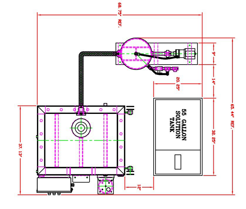
M Series chamber with external solution tank and side venting, showing required spacing between the tank and chamber for access, along with rear clearance for opening the chamber lid.
Important: chamber-only dimensions do not represent the full installed footprint. Solution tank position, DI feed, scrubber selection, exhaust routing, and power-vent requirements can all affect floor space, aisle clearance, and final chamber placement.
If you are replacing an existing steel chamber, confirm the internal size, tank location, utility connections, drain access, and vent path before purchase.
Custom and walk-in configurations are also available for higher throughput, oversized assemblies, or room-scale corrosion test programs.
M Series Salt Fog Chamber Options, Accessories, and Sample Handling
Plan DI water and ventilation before purchase. The standard M Series DI feed configuration assumes a pressurized DI water supply at the installation point. If pressurized DI water is not available, use the Bubble Tower DI Holding Tank / Hybrid Feed System (C910107).
Direct exterior venting is preferred whenever possible. If direct venting is not practical, the M Series can be configured with either the Non-Recirculating Scrubber / Jet Exhaust Assembly (C700200) or the Recirculating Scrubber / Jet Exhaust System (C260315). If the exhaust run exceeds 15 feet, add the Power Exhaust Vent Kit (C261820).
Standard Interior Configuration
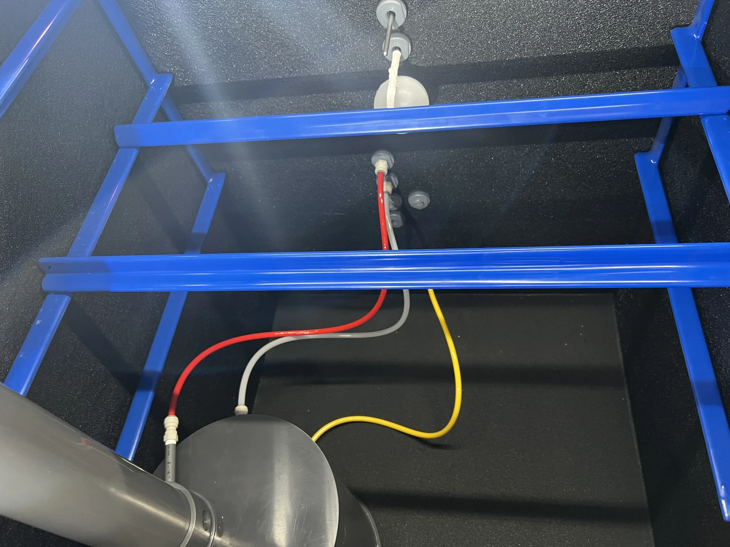
Standard chamber and solution-feed configuration: A new M Series chamber includes front and back ladder racks plus one Plastisol-coated support bar per ladder rack for sample support and suspension. Each support bar supports 50 lbs, providing 100 lbs of specimen capacity with the load evenly distributed across two bars. The image also shows the external solution reservoir and the connection lines used to supply the chamber. Additional slotted support bars, slotted support racks, and heavy-duty shelves can be added depending on specimen geometry and loading needs.
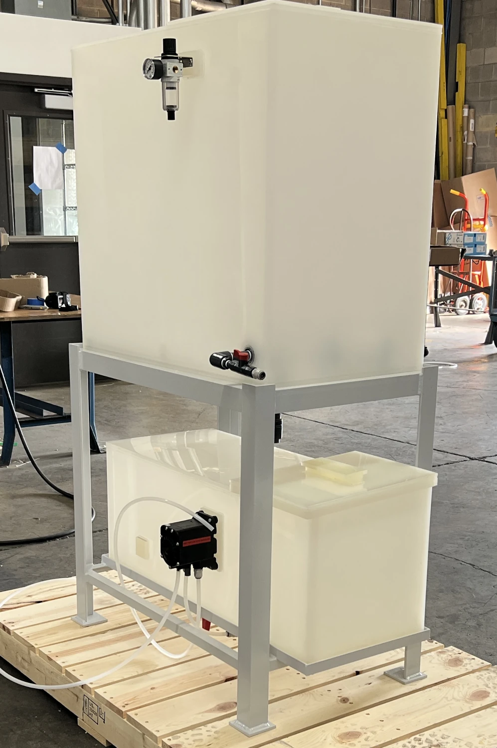
DI feed configuration: The standard M Series arrangement assumes pressurized DI water is available at the installation point. If a pressurized DI supply is not available, specify the optional Bubble Tower DI Holding Tank / Hybrid Feed System (C910107) shown here. The system provides a dedicated DI water source for the bubble tower while retaining the chamber's normal external solution-reservoir arrangement.
Chamber Configuration & Test Capability
These options change how the chamber operates or extend the test conditions it can support. Select them based on the governing test method and the operating conditions required by your program.
| Part Number | Item | Description / Important Notes | Image / Link |
|---|---|---|---|
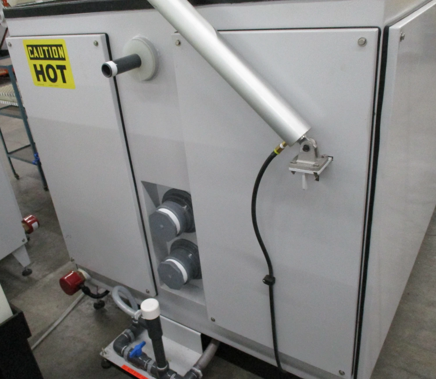
| — | High Temperature Package | Required when the specified chamber temperature exceeds 40 °C, including CASS testing. Upgrades chamber construction, cladding, and insulation for operation at temperatures up to 50 °C. |
Equipment Parts →
|
| — | Humidity Pipe Assembly | Supports humidity-oriented procedures when specified with the appropriate drain and operating configuration. Formal humidity methods should be identified at the time of order so the chamber can be configured correctly. | Equipment Parts → |
| C260455 | Wet Bottom Drain Assembly | Configures the chamber for wet-bottom operation by allowing a controlled depth of water to be retained on the chamber floor and drained when required. Wet-bottom operation is specified for most ASTM G85 Annex A2 testing and is stated as necessary for ASTM G85 Annex A3. ASTM G85 A2 includes a dry-bottom exception for 2000-series aluminum alloys and paint coatings requiring a less aggressive environment. | Equipment Parts → |
| — | SO2 Package | Injects metered customer-supplied SO2 into the chamber for ASTM G85 Annex A4, DIN 50018, JIS H 8502 SO2 variants, and related methods. | Equipment Parts → |
| — | Microprocessor / Cyclic Controls | Provides automatic timing and sequence control for procedures that require programmed operating steps. | Equipment Parts → |
| — | Independent Data Logger | Provides additional recording capability for chamber-related temperatures and operating data. | Equipment Parts → |
| C702200 | Automatic Shut-Down Timer | Allows automatic shutoff of air to the humidifying tower. Adjustable from 1 minute to 199 hours and 59 minutes. | Equipment Parts → |
| — | External Condensate Collection Package | Allows collection-rate checks without opening the chamber cover. | Equipment Parts → |
Specimen & Chamber Configuration
These options change how specimens, wiring, fixtures, or assemblies fit inside the exposure zone without changing the basic purpose of the chamber.
| Part Number | Item | Description / Important Notes | Image / Link |
|---|---|---|---|
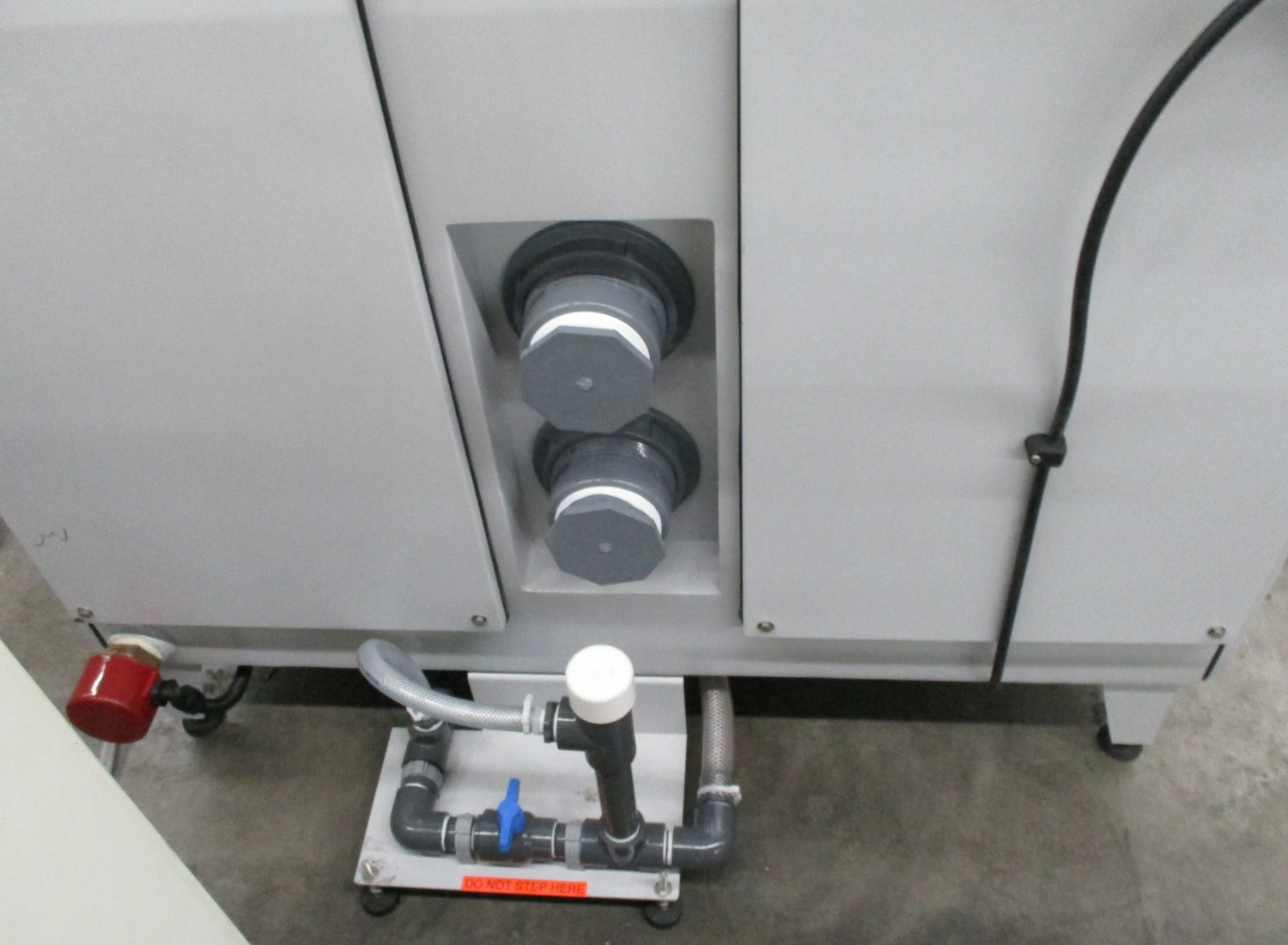
| — | Sample Access Ports | Vent-side ports for routing specimen wiring, tubing, or other connections between specimens inside the exposure zone and external equipment. Available port sizes and quantities depend on chamber size and test setup. The customer supplies the correctly sized grommet, bulkhead fitting, or other sealing method. |
Equipment Parts →
|
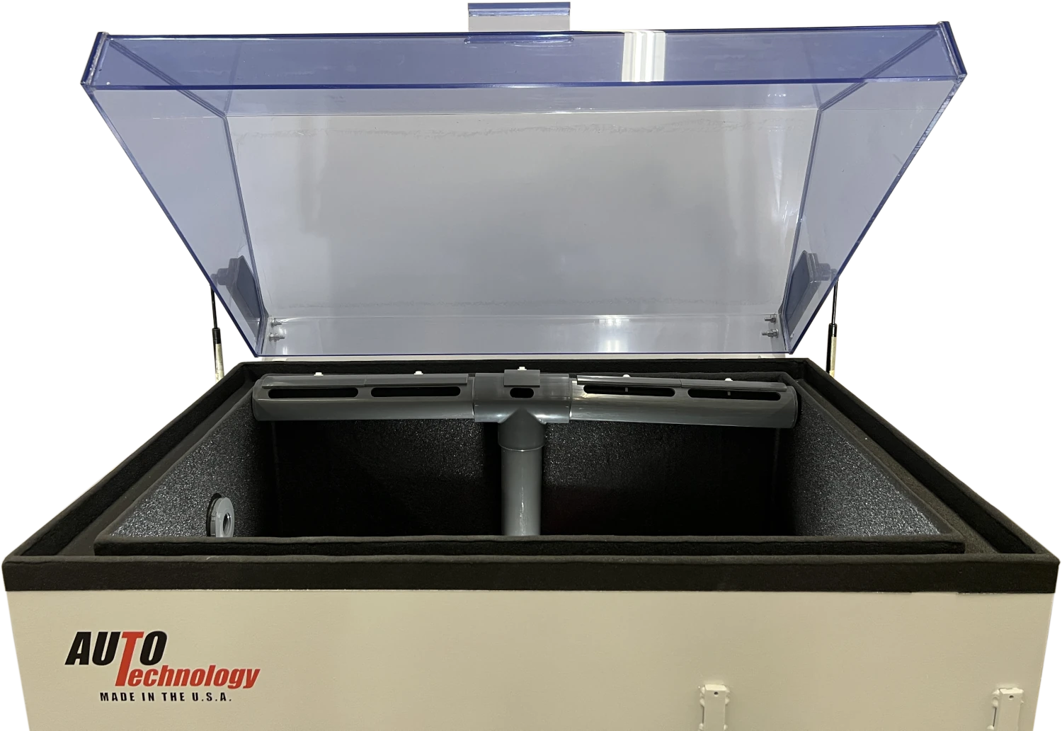
| — | Horizontal Dispersion Tower Configuration | Moves the fog dispersion system from the standard center position toward the back of the chamber to open more usable space for larger parts, assemblies, and special fixtures. |
Equipment Parts →
|
Utilities, Exhaust & Installation
Choose the exhaust configuration based on the facility. Direct exterior venting is preferred whenever practical. If direct venting is not available, choose either the Non-Recirculating Scrubber / Jet Exhaust Assembly (C700200) or the Recirculating Scrubber / Jet Exhaust System (C260315).
If the chamber also requires wet-bottom operation, the Combination Scrubber / Jet Exhaust + Wet Bottom Drain Package (C260300) combines those functions in one configured package. The Power Exhaust Vent Kit (C261820) serves a different purpose: it assists long direct exhaust runs rather than replacing a scrubber.
| Part Number | Item | Description / Important Notes | Image / Link |
|---|---|---|---|
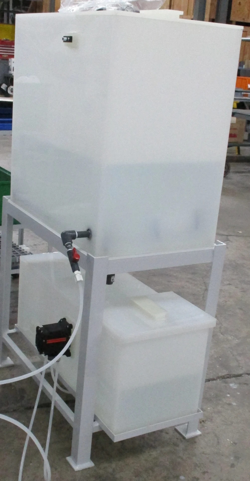
| C910107 | Bubble Tower DI Holding Tank / Hybrid Feed System | Required when pressurized DI water is not available at the installation point. The holding tank supplies DI water to the bubble tower without requiring a pressurized plant DI line. |
Equipment Parts →
|
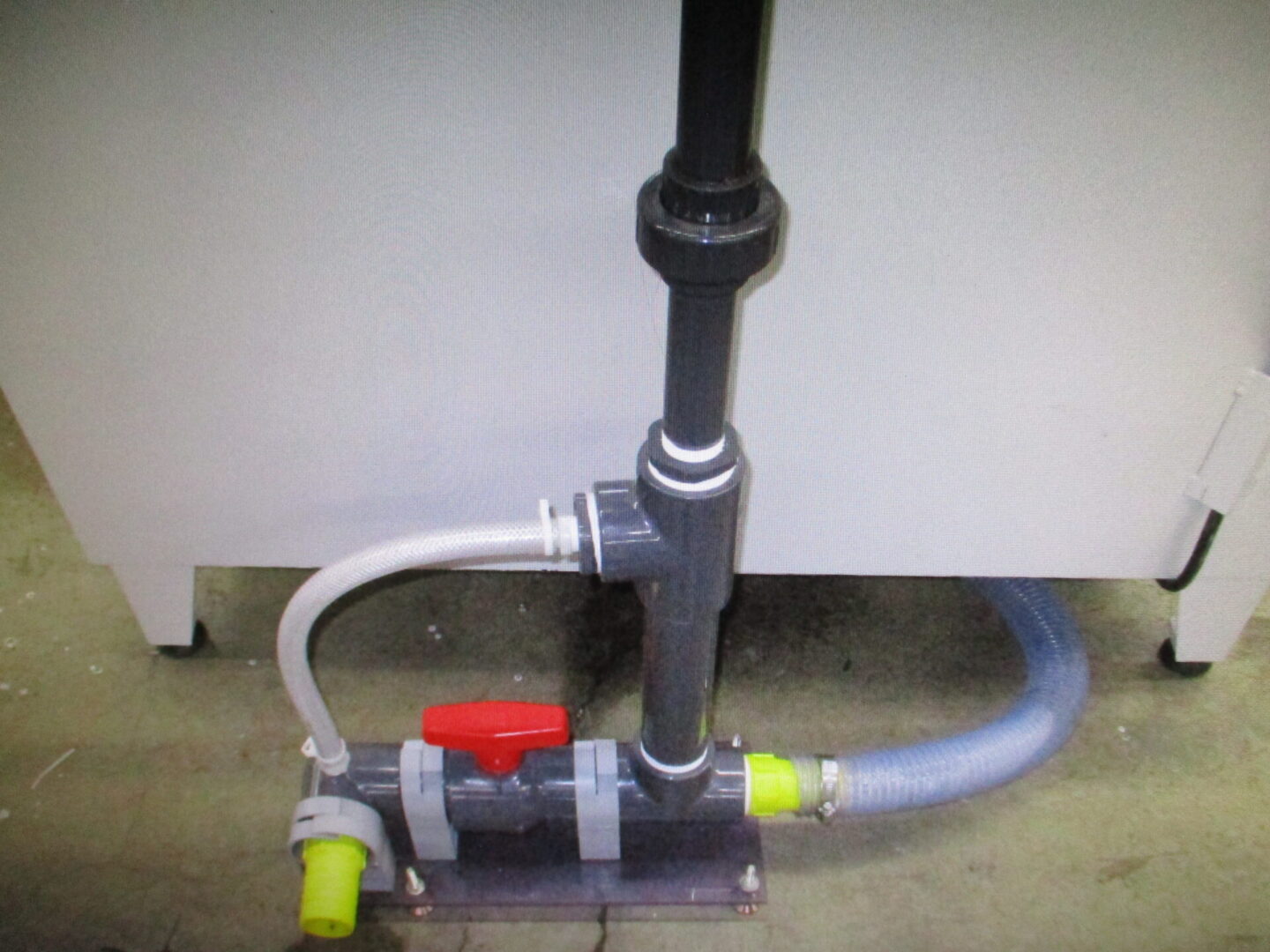
| C700200 | Non-Recirculating Scrubber / Jet Exhaust Assembly | Flow-through exhaust-treatment option for laboratories where direct exterior venting is not practical. Uses a continuous city-water supply and sends the used scrubber water to drain. Direct exterior venting remains preferred whenever practical. |
View Product →
|
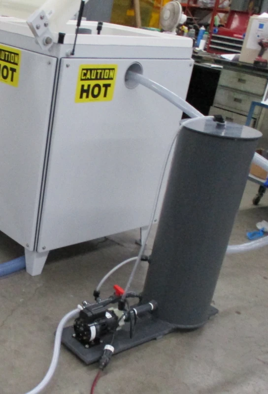
| C260315 | Recirculating Scrubber / Jet Exhaust System | Water-saving exhaust-treatment alternative for laboratories where direct exterior venting is not practical. Recirculates scrubber water instead of using continuous fresh-water flow. The existing M Series page notes potential water and sewer savings of up to $4,910 per year compared with a standard scrubber, based on 35 operating hours/week, a standard 3 GPM constant-flow scrubber, a recirculating model with a 7-gallon fill, and an assumed combined water/sewer rate of $15 per 1,000 gallons. |
View Product →
|
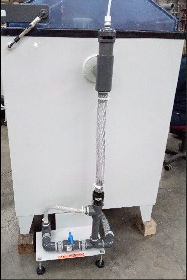
| C260300 | Combination Scrubber / Jet Exhaust + Wet Bottom Drain Package | Combined configuration for laboratories that need both exhaust treatment and wet-bottom capability. Includes the scrubber / jet exhaust arrangement with regulator together with the wet-bottom drain configuration, avoiding the need to treat those functions as separate facility selections. |
Equipment Parts →
|
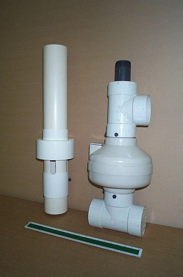
| C261820 | Power Exhaust Vent Kit | Recommended when a direct exhaust run exceeds 15 feet to actively pull exhaust from the chamber and maintain proper airflow through the exhaust system. This assists exterior venting; it is not a substitute for a scrubber where exhaust treatment is required. |
Equipment Parts →
|
| C261800 | Installation Kit | Installation components for setting up an M Series salt fog chamber. | View Product → |
Simple humidity operation: For basic legacy-style humidity exposure, the chamber can be run with DI water in the solution tank. Formal humidity procedures such as ASTM D2247 should still be specified up front so the correct humidity and drain configuration can be supplied.
Horizontal vs. Vertical Fog Tower Configuration
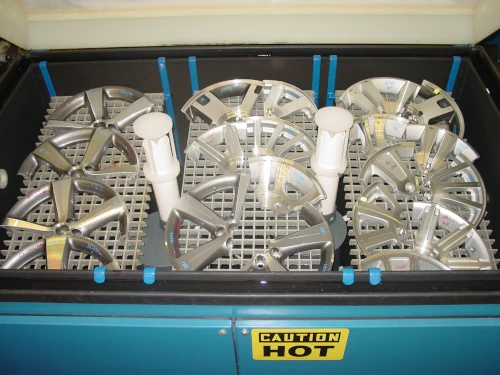
Standard Vertical Tower
Center-mounted fog tower with shelves shown for comparison of the standard loading layout.
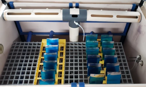
Optional Horizontal Tower
Moves the fog dispersion system toward the back wall to open the center of the chamber.
Racking and Sample Handling
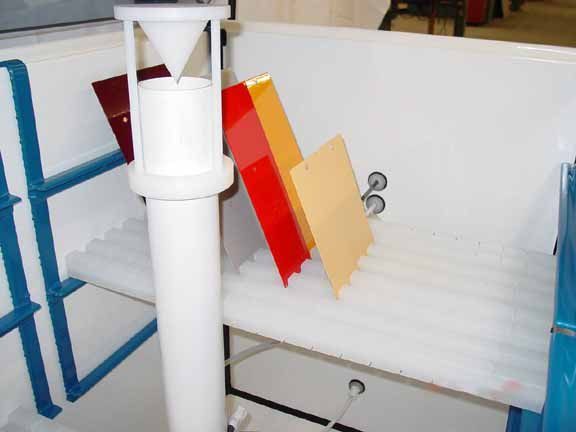
M Series support bars provide 50 lbs of specimen capacity per bar. A two-bar setup safely supports 100 lbs with the load evenly distributed across both bars.
| Part Number | Item | Description / Important Notes | Image / Link |
|---|---|---|---|
| — | Slotted Support Bars | Optional specimen supports for positioning corrosion test panels and coupons within the standard M Series ladder-rack system. Each support bar supports 50 lbs. |
Equipment Parts →
|
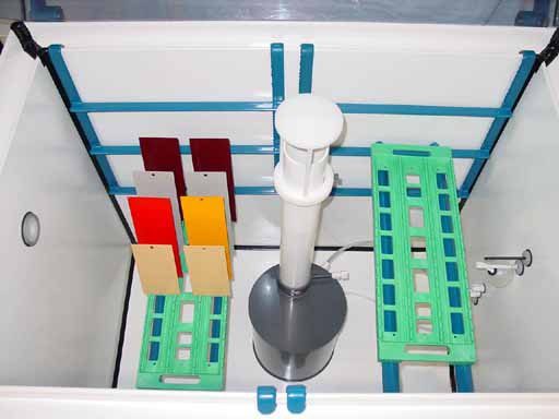
| — | Slotted Support Racks | Optional rack-style support for organizing multiple corrosion test panels or coupons within the chamber. |
Equipment Parts →
|
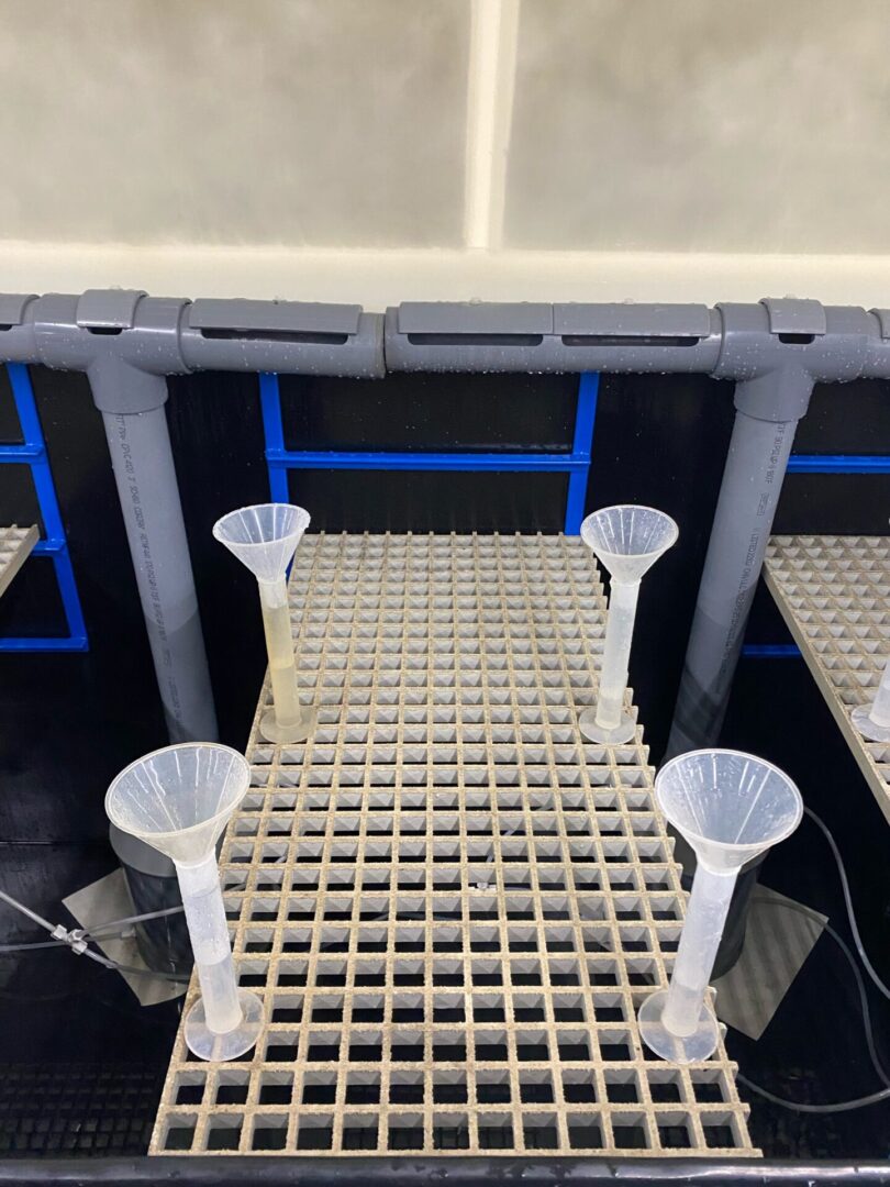
| — | Heavy-Duty Shelves | Optional shelves for supporting larger or heavier specimen loads on the standard ladder-rack system. |
Equipment Parts →
|
Need replacement parts, salts, solutions, or common accessories? Buy direct from the Auto Technology Equipment Parts Store.
Specs & Installation
Utilities, Electrical, and Operating Data
| Model | 110/1/60 | 208/1/60 | 208/3/60 | 240/1/60 | 240/3/60 | 460/3/60 | 575/3/60 |
|---|---|---|---|---|---|---|---|
| 15 | 34 Amps | 21 Amps | 21 Amps | 20 Amps | 18 Amps | 7 Amps | 10 Amps |
| 22 | 34 Amps | 21 Amps | 21 Amps | 20 Amps | 18 Amps | 7 Amps | 10 Amps |
| 23 | — | — | 34 Amps | — | 30 Amps | 15 Amps | 13 Amps |
| 24 | — | — | 34 Amps | — | 30 Amps | 15 Amps | 13 Amps |
| 410 | — | — | 34 Amps | — | 30 Amps | 15 Amps | 13 Amps |
| 512 | — | — | — | — | 30 Amps | 15 Amps | 13 Amps |
Power configuration note: A dash (—) indicates that the corresponding voltage, phase, and frequency configuration is not supported for that chamber model.
Included Labware, Weight, and Daily Consumption
| Model | Cover Lifter Type | Crated Weight | Funnels | Cylinders | Estimated Daily Solution Use | Estimated Daily DI Water Use |
|---|---|---|---|---|---|---|
| 15 | Gas | 1000 lbs | 2 | 2 | 10 gal | 10 gal |
| 22 | Gas | 1350 lbs | 2 | 2 | 10 gal | 10 gal |
| 23 | Air | 2000 lbs | 4 | 4 | 20 gal | 20 gal |
| 24 | Air | 3000 lbs | 4 | 4 | 20 gal | 20 gal |
| 410 | Air | -- | 6 | 6 | 30 gal | 30 gal |
| 512 | Air | -- | 18 | 18 | 35 gal | 35 gal |
Facilities, Utilities, and Installation
Water and Drain Connections
- Water jacket drain: 1.25 in copper or galvanized steel
- Chamber drain: 1.25 in O.D. PVC
- DI water supply: 3/8 in O.D. poly tubing from a pressurized DI water source, typically 15–30 psi
Compressed Air
- Compressed air supply: 3/8 in O.D. poly tubing from a clean, dry air source
- Typical pressure range: 65–85 psi
Ventilation Requirements
- Salt fog cabinet exhaust should vent directly to the exterior of the building whenever possible
- Do not connect the chamber exhaust to a shared plenum or duct serving other instruments
- Use 1.25 in PVC piping for the chamber vent connection
- Power vent recommended when exhaust runs exceed 15 ft
Facility Environment
- Flat, level floor capable of supporting the installed chamber weight
- Nearby floor drain recommended for condensate and cleaning operations
- Room temperature: 20–25 °C (68–77 °F)
- Room humidity: 45 ±10% RH, non-condensing
Installation environment: Chamber operation depends on stable room conditions, correct utilities, drainage, and exhaust.
Install the chamber in a controlled laboratory area. Avoid warehouses, boiler rooms, garages, factory floors, paint rooms, powder mixing rooms, and other locations with excessive dust, frequent door opening, or large changes in temperature, humidity, or air pressure.
For a complete overview of laboratory layout considerations including utilities, ventilation, and spacing requirements, see our corrosion chamber room requirements guide.
Ordering Information
- Please specify voltage and phase when ordering
- Prices quoted are valid for 30 days
- Terms: 50% down payment, 50% Net 30 days (pending credit approval)
- Shipping: F.O.B. Strongsville, Ohio
- Delivery: based on production levels at time order is received and after receipt of down payment
Photos & Video
Chamber Design
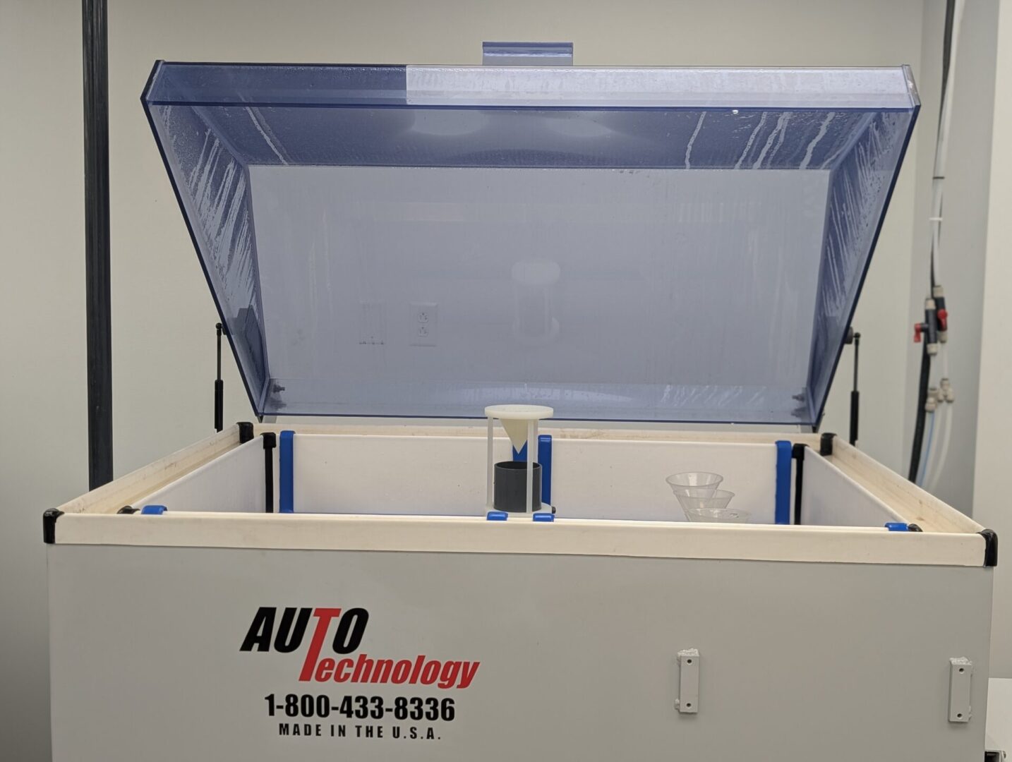
M Series salt fog chamber installed in a laboratory environment for standards-driven salt spray and humidity testing.
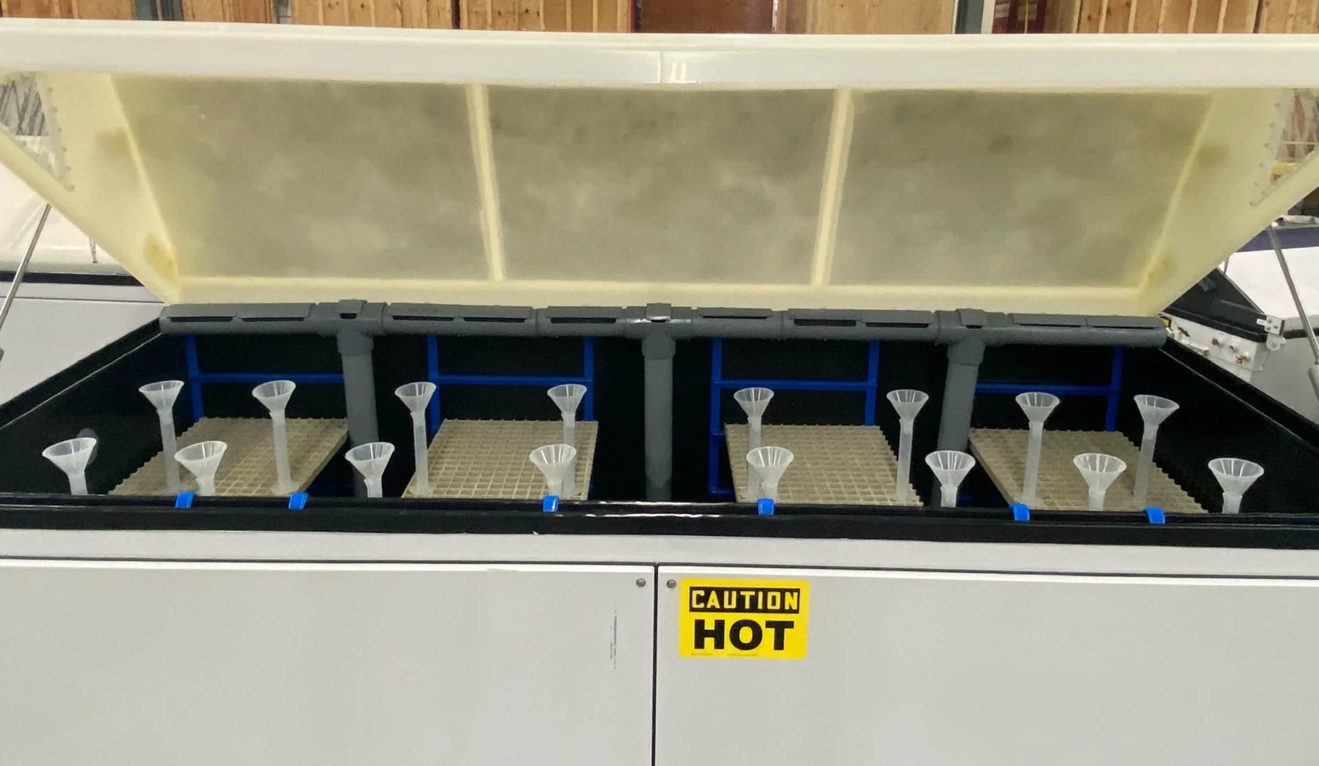
Chamber interior showing exposure zone layout, specimen support hardware, and fog-generation components.
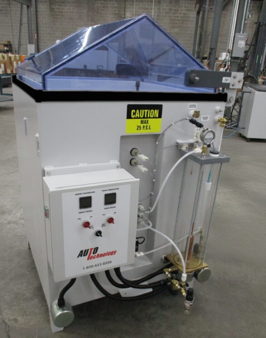
Bubble tower conditioning hardware and chamber controls used to support stable salt fog generation.
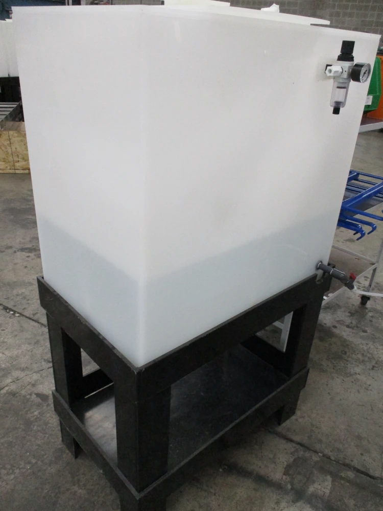
Solution tank and mixing system used to maintain consistent salt solution delivery during testing.
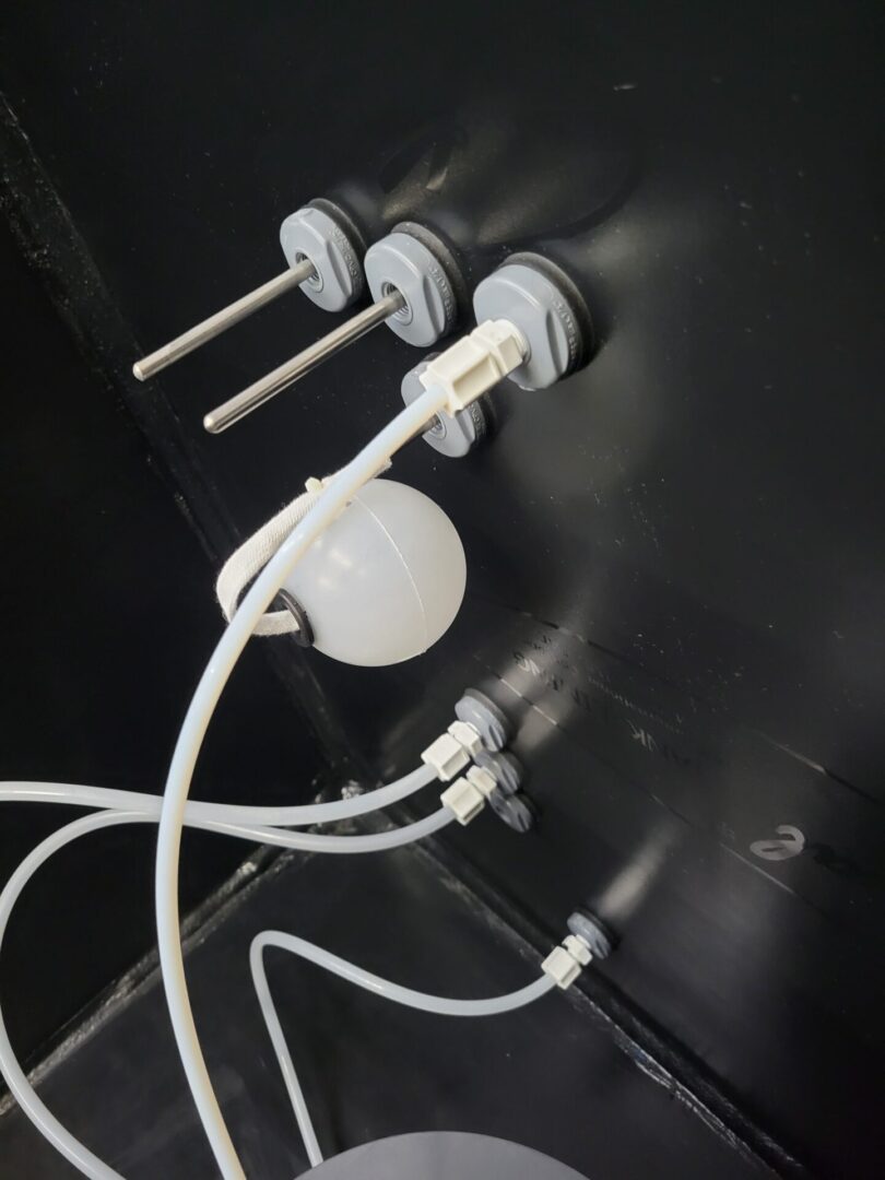
Wet and dry RTDs installed inside the M Series chamber for monitoring cabinet conditions during salt fog and humidity testing.
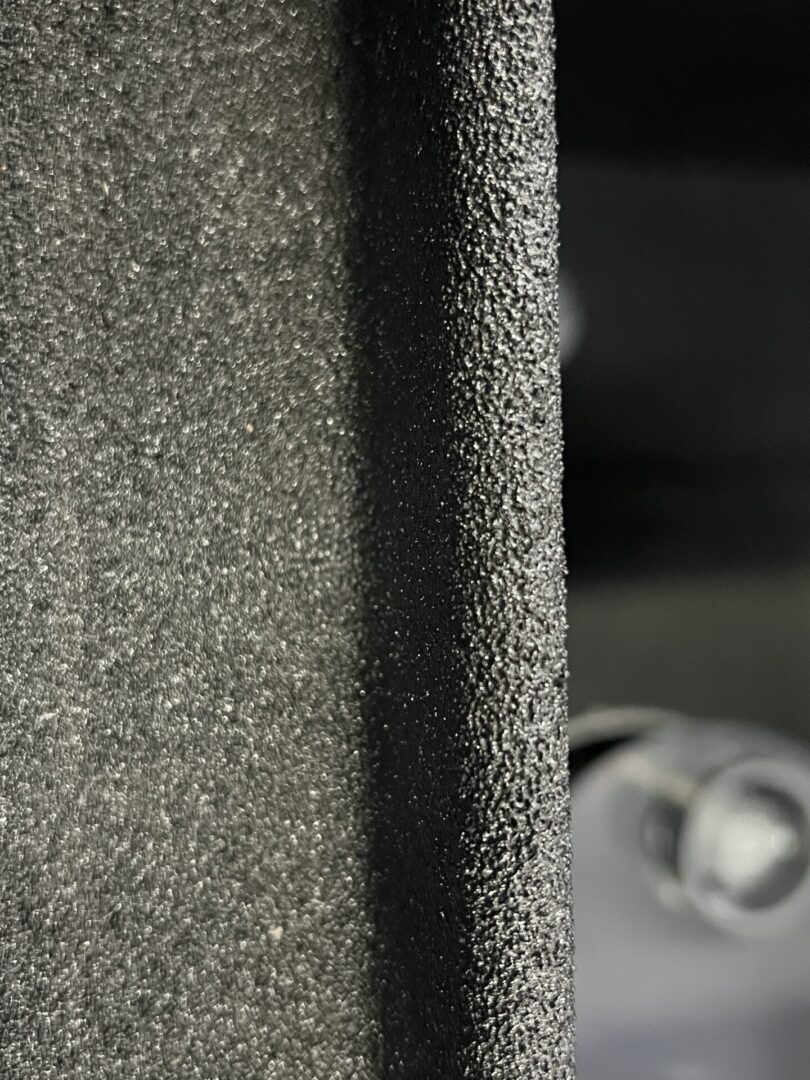
Close-up of the M Series black polyurea liner showing the durable, corrosion-resistant interior chamber surface.
Auto Technology ASTM B117 and ISO 9227 Corrosion Chamber Introduction
Salt Spray Test Supplies, Calibration, and Service
| Item | Purpose |
|---|---|
| ASTM B117 Salt | Salt conforming to ASTM B117 for solution preparation |
| Calibration Certificate | Documentation for chamber-related calibration records where required |
| pH Meter Kit | For checking mixed solution and collected condensate pH |
| Mass Loss Test Panels | Panels for ASTM B117-related mass-loss or chamber-verification work |
| DI Water Drum | Bulk DI water supply for chamber use where needed |
| CASS Solution Drum | Prepared solution support for CASS-related work |
| Premixed 5% Salt Solution | Premixed 5% salt solution for ASTM B117 salt spray testing |
| Salt Fog Training Class | Operator and quality training for correct chamber use and maintenance |
| Start-Up Service | Commissioning support after installation |
| Start-Up Kit | Basic ASTM B117-related test accessories |
| Preventive Maintenance Kits | Annual maintenance replacement items |
| Accredited Calibration Support | Qualified service support for calibration and quality-system needs |
Replacement parts, salt spray test accessories, salts, prepared solutions, calibration items, and maintenance products are available through the Auto Technology Equipment Parts store.
FAQ
Why would a laboratory specify a traditional steel salt spray chamber?
Laboratories replacing existing steel salt spray equipment or maintaining long-running ASTM B117 and related qualification programs may specify a similar steel, water-jacket-heated chamber architecture for consistency with established equipment and procedures.
Can the M Series run 100% humidity?
DI water can be used in the solution tank for water-fog humidity exposure. If you need a formal humidity procedure such as ASTM D2247 or another humidity-specific method, the chamber should be configured appropriately at the time of order.
What types of humidity testing can the M Series perform?
The M Series can perform water fog humidity testing by filling the solution tank with DI water. Humidified compressed air from the bubble tower passes through the atomizer, creating a fine aerosol of water droplets throughout the exposure zone.
Condensing humidity testing is available when the chamber is equipped with an optional wet bottom and bubbler system. Water vapor generated inside the chamber condenses on cooler specimen surfaces, creating a continuous moisture film.
How many test panels can fit inside an M Series chamber?
When using the Auto Technology 23" × 8.5" Slotted Test Panel Tray , the following capacities can typically be achieved with small, flat test panels:
- M Series Size 15: Approximately 80 panels (2 racks)
- M Series Size 22: Approximately 200 panels (5 racks)
- M Series Size 23: Approximately 320 panels (8 racks)
- M Series Size 24: Approximately 400 panels (10 racks)
These capacities represent maximum capacity for small, flat coupons. Larger flat panels or panels placed too closely together may create shadowing effects that interfere with proper fog exposure and reduce the practical number of specimens that can be tested at one time.
What if my lab does not have pressurized DI water?
If your lab does not have pressurized DI water, the Bubble Tower DI Holding Tank / Hybrid Feed System is the common alternative.
What if my parts are too large for the standard center tower layout?
Horizontal dispersion towers are available for larger parts and assemblies. This moves the fog dispersion arrangement away from the center and opens more usable space inside the exposure zone.
What comes standard with a new M Series chamber?
A new chamber includes front and back ladder racks plus one Plastisol-coated support bar per ladder rack for sample support and suspension. Each support bar supports 50 lbs, so a two-bar setup safely supports 100 lbs with the load evenly distributed across both bars. Additional slotted bars, trays, and heavy-duty shelves are available depending on your parts and loading needs.
What else do I need besides the chamber to run ASTM B117?
Most labs also need a pH meter, hydrometer or salimeter, collection funnels and graduated cylinders, a way to record operating data, proper water and salt, and—depending on the quality system—training, accredited calibration, and proficiency testing support.