
ENGINEERED TO OUTPERFORM: A HIGHER STANDARD OF CORROSION TESTING QUALITY

Auto Technology builds corrosion chambers for the temperature, humidity, fog or spray delivery, airflow, solution conditions, dwell times, transitions, and records required by ASTM, ISO, SAE, OEM, and customer test methods. Chamber configuration is based on the applicable method and revision, the specimen load, and the usable exposure volume.
Low-cost imported chambers sold through Amazon and other online marketplaces may be listed and supported by resellers that did not engineer or manufacture the equipment. Every ATC corrosion chamber is engineered, built, tested, and supported in Cleveland, Ohio, by the company responsible for its design and long-term service.

ATC corrosion chambers are engineered, built, tested, and supported in Cleveland, Ohio.
ATC Chambers vs. Low-Cost Alternatives
| Item | ATC | Confirm Before Buying an Imported Chamber |
|---|---|---|
| Engineering and support | Designed, manufactured, tested, serviced, and supported by ATC in Cleveland, Ohio | Whether the seller designed or built the chamber, where replacement parts are stocked, and who provides technical service |
| Method capability | Configuration is reviewed against the standard, revision, cycle, and expected load | Whether the listed program is supported by the required hardware and control range |
| Capacity | Published as usable exposure volume | Whether the advertised volume includes lid or other non-working space |
| Fog distribution | Baffled fog tower conditions and distributes fog before specimen exposure | Whether specimens receive distributed fog or direct nozzle impingement |
| Solution conditioning | Internal reservoir brings solution near chamber temperature before atomization | How solution temperature affects startup, replenishment, and recovery |
| Parts and service | Industrial components, documented replacement paths, and verification of affected functions | Whether replacement parts can change the exposure without detection |
Corrosion Testing Experience Behind the Equipment
Auto Technology's chamber lineage reaches back to GS Equipment, which manufactured purpose-built salt spray chambers in the 1950s as commercial equipment helped laboratories run ASTM B117 more consistently. That chamber-building experience continued through Harshaw, Gulf, Kaiser, Engelhard, and Atotech before becoming part of Auto Technology. That manufacturing continuity remains in Cleveland.
Kevin A. Smith represented Auto Technology on the team that published the 2003 SAE paper documenting the development of SAE J2334. Since 2008, ATC's contract laboratory has run ASTM B117, SAE J2334, GMW 14872, Ford L-467, and other corrosion methods. Daily laboratory operation provides direct information about specimen loading, transition performance, maintenance, control materials, and chamber response.
Conditions That Define the Test
Continuous salt fog methods such as ASTM B117 and ISO 9227 differ from cyclic methods such as SAE J2334. The applicable method determines which conditions must be controlled and recorded.
| Variable | Effect on Exposure | Common Sources of Drift |
|---|---|---|
| Temperature | Reaction rate, evaporation, condensation, and recovery | Overshoot, gradients, slow recovery, sensor error |
| Humidity | Electrolyte persistence, drying, and time of wetness | Sensor drift, poor airflow, unstable humidity generation |
| Fog or spray | Solution deposition, droplet behavior, and wetting | Nozzle wear, air-pressure drift, contamination, poor dispersion |
| Transitions | Rewetting, drying, and cyclic stress | Ramp rate, thermal mass, airflow, purge, slow recovery |
| Airflow | Oxygen availability, drying rate, and exposure uniformity | Fan performance, deposits, duct restrictions, chamber loading |
| Solution chemistry | Conductivity, pH, chloride loading, and corrosion mechanism | Water or salt quality, pH drift, contamination, mixing error |
Verification and Test-History Control
Qualification data remain comparable only when the chamber and laboratory practices remain controlled. Verification must cover initial acceptance, routine operation, service changes, and the records used to compare current results with earlier work.
| When | Verification | Record |
|---|---|---|
| Installation or acceptance | Utilities, sensor calibration, programmed sequence, safety functions, and conditions within the defined working volume under an agreed load | Acceptance and calibration records |
| During testing | Measurements required by the method, including collection rate, temperature, humidity, solution chemistry, and cycle timing where applicable | Test log, controller history, alarms, and deviations |
| After service | Every chamber function affected by a replaced or adjusted component | Service record and post-service verification results |
| Across months or years | Control panels, reference coupons, mass-loss data, loading practice, and trend limits used by the laboratory | Historical control data and configuration history |
Chamber Design
Usable Exposure Volume
ATC publishes the working space in which specimens can be positioned and receive the intended exposure. Space inside the lid is not counted as usable test capacity.
Baffled Fog Delivery
ATC's baffled fog tower separates atomization from specimen exposure. The baffles remove large droplets and distribute conditioned fog through the chamber, reducing direct nozzle impingement and supporting uniform collection across the working area.
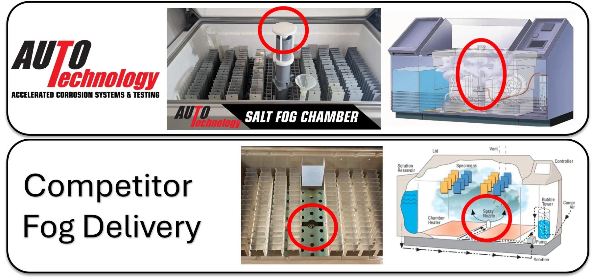
Baffled fog delivery conditions and distributes the fog before it reaches the specimens.
Conditioned Solution Reservoir
Locating the solution reservoir within the conditioned chamber environment brings the solution near chamber temperature before atomization. This limits the disturbance caused by feeding cooler solution from an external reservoir. ATC Size 20 and Size 40 chambers use a 60-gallon internal reservoir.
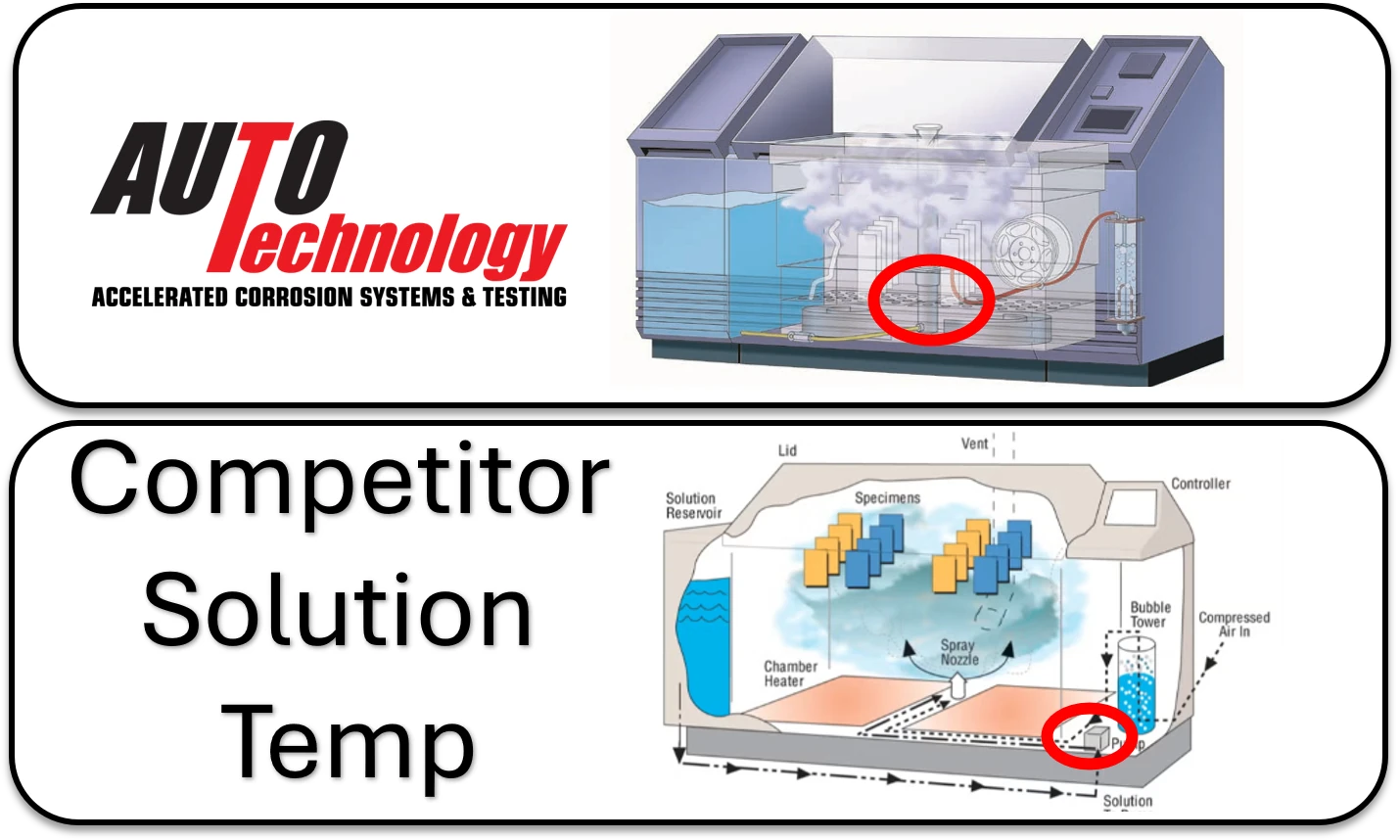
An internal reservoir conditions the solution before it enters the fog-delivery system.
Components That Can Change the Exposure
Wear, adjustment, or replacement can change chamber performance even when the controller program remains unchanged. ATC documents replacement paths and identifies the chamber functions that must be checked after service.
| System | Possible Change | Post-Service Check |
|---|---|---|
| Atomizer, nozzle, fog tower, or spray bar | Droplet distribution, collection rate, wetting | Pressure, collection, and distribution |
| Temperature or humidity sensor | Measured condition and controller response | Calibration and response at relevant setpoints |
| Heater, cooling, steam, or humidification system | Recovery, condensation, drying, dwell stability | Setpoint stability, ramps, transitions, and uniformity |
| Fan, blower, purge, damper, or ducting | Airflow, fog distribution, oxygen supply, drying | Air movement and exposure uniformity under the defined load |
| Pump, valve, regulator, tubing, or filter | Solution or air delivery | Flow, pressure, leaks, collection, and cycle response |
| Controller, relay, I/O, or software | Sequence timing, alarms, data, and traceability | Program execution, inputs, outputs, alarms, and records |
Frequently Asked Questions
Can one corrosion chamber run every listed standard?
No. Standards can require different humidity ranges, temperature transitions, fog or direct spray systems, drying capability, cooling, solution handling, and control materials. The chamber hardware and control range must be checked against the applicable method and revision.
Does completing the programmed cycle prove conformance?
No. The laboratory must also have the measurements and records required by the method showing that the specified conditions remained within their limits.
Can an older chamber be replaced without losing historical comparability?
Not automatically. The laboratory should define its historical controls, run overlap or comparison testing where appropriate, and document loading, calibration, collection, control-panel, coupon, or mass-loss data needed to establish continuity.
Does ATC include the lid when stating chamber capacity?
No. ATC publishes usable exposure volume. Space inside the lid is excluded because specimens cannot be positioned there as part of the defined working area.