
FIRST-TIME SETUP - C SERIES CORROSION CHAMBER (G85 A5 & B117)

Set up the utilities and prepare your C Series chamber for ASTM G85 Annex A5 or ASTM B117 testing.
Before installation or operation, read the C Series Instruction Manual supplied with your chamber. Use it to identify the connections, valves, and controls on your unit.
- ASTM G85 Annex A5
- ASTM B117
ASTM G85 Annex A5
ASTM G85 Annex A5, also called Prohesion, was developed after researchers found that some protective primers performed well outdoors in industrial environments but poorly in continuous salt spray. A5 alternates one hour of dilute electrolyte fog at room conditions with one hour of heated dry-off to expose specimens to repeated wetting and drying. The fog solution contains 0.05% sodium chloride and 0.35% ammonium sulfate by mass.
In Auto Technology’s default C Series A5 setup, the chamber fills the wet bottom with unheated water during fogging while the immersion heater is off. The chamber drains the wet bottom during dry-off and refills it when the next fog step begins.
First-Time Utility Connections
Refer to the C Series Instruction Manual and your chamber drawings for utility ratings and connection locations before connecting power, air, water, exhaust, or drainage.
Electrical power
Provide the supply specified on the nameplate and drawings. Verify voltage, frequency, phase, circuit rating, and disconnect requirements. If you have a scrubber, check its nameplate before connecting it to a 120 V AC supply.
Exhaust and scrubber
If you have a scrubber, connect the chamber vent to its inlet and add approximately 19 litres (5 US gallons) of water. Check the water every few days at first. If you have no scrubber, route the chamber exhaust outdoors. Refer to the C Series Instruction Manual for vent connections and the installation guide below for exhaust routing.
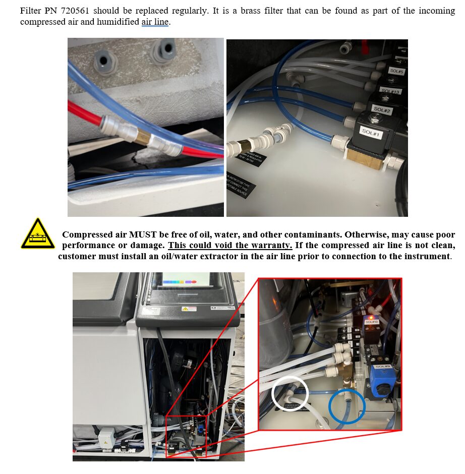
Compressed air
Connect a continuous supply of clean, dry, oil-free compressed air at 65–85 psi (4.5–5.9 bar) while the chamber is operating.
Gravity drainage
Route the drain lines downhill into an open floor drain. Size 20 wet-bottom operation can discharge approximately 106 litres (28 US gallons) each time the chamber empties. Confirm with the local wastewater authority whether chamber runoff, leftover fog solution, and spent scrubber water may be discharged.
Choose a Water Supply for ASTM G85 Annex A5
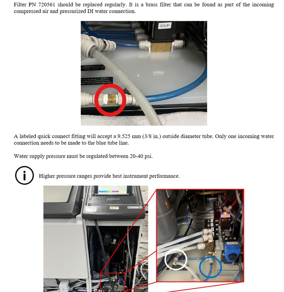
Refer to the C Series Instruction Manual for the water inlet location, pressure, and tubing requirements. The chamber water inlet and the fog solution tank are separate.
With a Type IV DI water connection
Connect a pressurized ASTM D1193 Type IV deionized (DI) water supply to the chamber inlet. Ensure your supply can deliver enough water for each wet-bottom fill and keep up with repeated fills throughout the test.
- For a C Series Size 20, allow approximately 106 litres (28 US gallons) per fill or 1,270 litres (336 US gallons) per 24 hours of continuous wet-bottom A5 cycling.
- Fill the solution tank with premixed A5 solution or prepare it with Type IV DI water. Allow for this additional DI water if mixing on site.
- Keep the Type IV DI supply connected if you later switch to B117.
ASTM B117 requires a Type IV DI water connection. Switch the chamber inlet to a pressurized Type IV DI supply before running B117.
Use the clean filtered water only for the A5 wet bottom. It cannot be used to mix the A5 fog solution. Use premixed A5 solution or mix it with Type IV DI water from a separate source.
Locate the water inlet
Refer to the C Series Instruction Manual for the water inlet location, supply pressure, and tubing size. Click the excerpt to enlarge it.
Bypass the Bubble Tower for ASTM G85 Annex A5
Set the bypass valves before running A5. Refer to the C Series Instruction Manual for the valve locations and labels on your chamber.
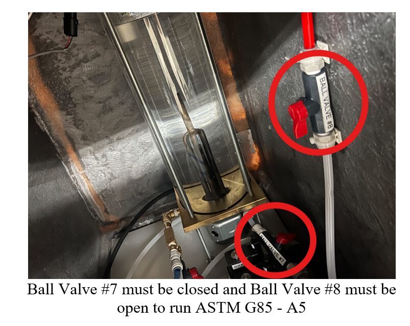
On a chamber with valves labeled B7 and B8, close B7 (handle perpendicular to the flow path) and open B8 (handle parallel to the flow path). This routes non-humidified atomizing air directly to the fog nozzle. Confirm the valve labels against your manual.
C Series Touchscreen
Refer to the C Series Instruction Manual for your touchscreen controls and available test profiles.
ASTM G85 Annex A5 programming example
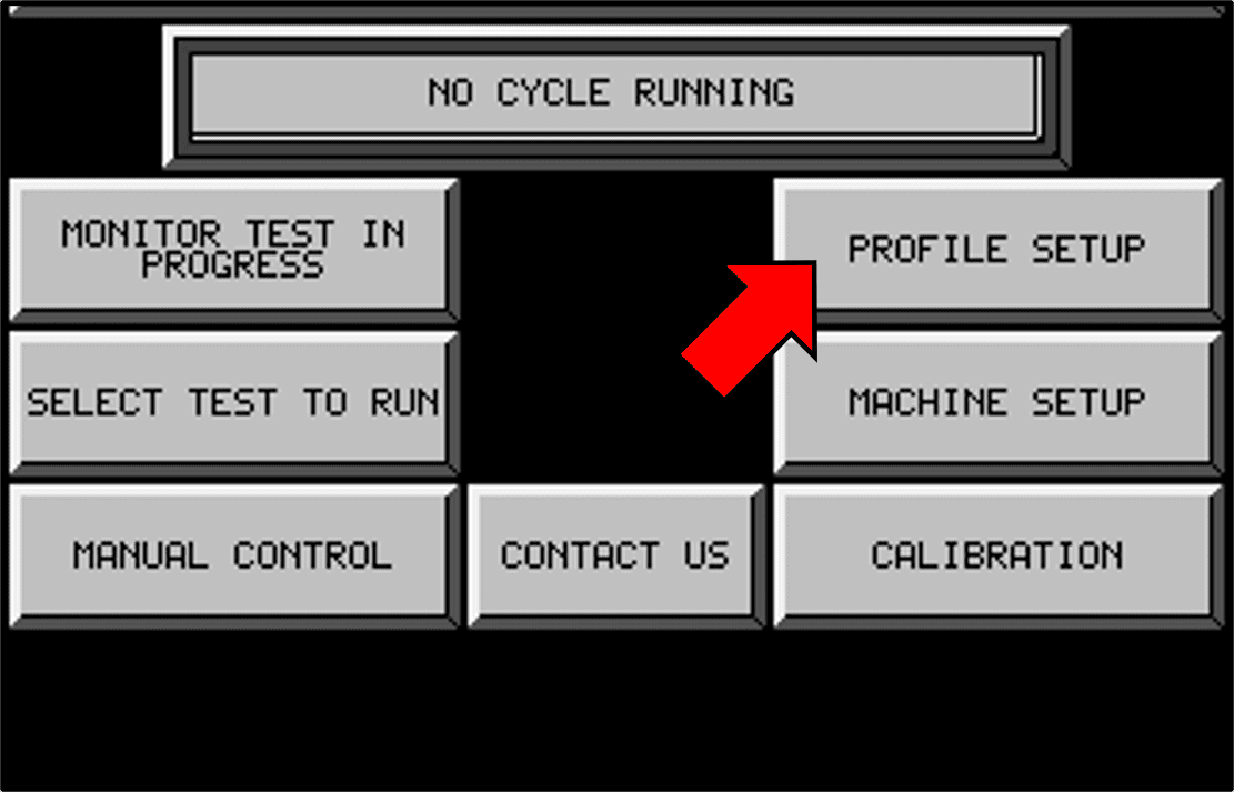
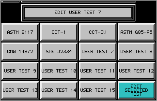
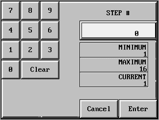
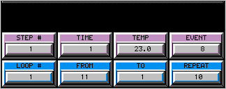
On the touchscreen, go to Main Menu → Profile Setup, select an unused User Test (7–15), and choose Edit Selected Test. On Profile Setup Page 2, select STEP # before entering its TIME, TEMP, and EVENT. Press ENTER after each value. Use CLEAR to correct a mistyped entry.
| Step | Time | Temperature setting | Event |
|---|---|---|---|
| 1 — Fog | 60 minutes | Below measured room temperature, for example 20 °C in a 24 °C room | 1 |
| 2 — Dry-off | 60 minutes | 35 °C | 4 |
Use a supported fog setpoint below the measured room temperature to keep the heater off. This setting provides no active cooling. Verify that the exposure zone is at ambient conditions when fogging begins. Annex A5 gives room conditions of 24 °C ± 3 °C and below 75% RH.
Set LOOP # = 1, FROM = 2, and TO = 1 to return from dry-off to fog. The controller runs the first two-hour cycle once, then repeats it the number of times entered in SET. Use SET = total cycles − 1.
| Exposure | Total cycles | SET |
|---|---|---|
| 24 hours | 12 | 11 |
| 48 hours | 24 | 23 |
| 100 hours | 50 | 49 |
| 168 hours | 84 | 83 |
| 360 hours | 180 | 179 |
Before starting, check the fog solution, room conditions, and bubble tower bypass. Review both steps and the loop entries on the touchscreen.
To start the test, go to Main Menu → Select Test to Run, select your programmed profile, confirm its name in the status bar, and press Start. The controller stops after the final dry-off step.
Check dry-off and the return to ambient
Verify that the exposure zone reaches 35 °C ± 1.5 °C within 45 minutes of switching to dry-off and stays in range for the remainder of the step. The fresh-air purge must remove all visible moisture from the specimens within those same 45 minutes. Check the exposure-zone temperature again when the next fog step begins.
If the next fog step starts too warm, check the room conditions and chamber setup first. Keep the full 60-minute dry-off at 35 °C for the standard A5 profile.
If your governing procedure or approving authority permits a modified profile, the programming guide shows a 45-minute dry-off at 35 °C followed by 15 minutes at a supported setpoint below ambient. Use Event 4 for both steps and set FROM = 3 and TO = 1. Confirm approval before using this profile. Reducing the setpoint can conflict with the A5 dry-off temperature requirement.
Set Up the Chamber for ASTM B117
Refer to the C Series Instruction Manual for the B117 profile and valve positions. B117 uses continuous salt fog. For the C Series wet-bottom setup, fill the wet bottom at the start and maintain the water level during the test.
- Connect a pressurized ASTM D1193 Type IV DI water supply to the chamber inlet for both the wet bottom and the bubble tower. Allow about 106 litres (28 US gallons) for the initial Size 20 fill, plus make-up water.
- Set the valves so atomizing air passes through the bubble tower before reaching the nozzle.
- Fill the separate solution tank with premixed B117 solution or prepare it with Type IV DI water and salt suitable for B117.
Frequently Asked Questions
Can I run ASTM G85 A5 without a Type IV DI water connection?
Yes. For wet-bottom A5, connect pressurized, clean filtered water to the chamber inlet. Use premixed A5 fog solution or prepare it with Type IV DI water from a separate source.
Can I run ASTM B117 with clean filtered water connected to the chamber?
B117 requires a pressurized ASTM D1193 Type IV DI water connection on the C Series. Switch the chamber inlet to Type IV DI water before running B117. This supply feeds both the wet bottom and the bubble tower.
Can I run A5 with fog and no wet bottom?
Yes. Run the fog step without a wet bottom, followed by heated dry-off. Refer to the C Series Instruction Manual and confirm the setup for your chamber with Auto Technology.
Where should I route the chamber exhaust?
Connect the chamber vent to the scrubber inlet if you have a scrubber. Otherwise, route the exhaust outdoors. Refer to the C Series Instruction Manual and chamber installation guide for your configuration.
C Series Installation and Test Resources
Keep the C Series Instruction Manual supplied with your chamber on hand during installation and operation.