
X SERIES CHAMBER PERFORMANCE FOR FORD L-467

The Auto Technology X Series uses Advanced Climate Control and a Swaying Spray Bar to perform Ford L-467 cyclic corrosion testing. Review the chamber requirements, equipment, measured climate cycles, gauge-loss measurements, and mass-loss results below.

- Advanced Climate Control
Cooling, Heating & RH - Swaying Spray Bar
Direct Solution Application - PC Sequencing
Spray & Climate Steps - Measured Performance
Climate & Panel Results
Ford L-467 Requirements
Ford L-467 combines direct salt-solution application with controlled cooling, heating, humidity, and drying. The first five days repeat a 24-hour cycle; the final two days remain at 50 °C and 70% RH. The chamber must perform the following exposures and transitions.
| Ford L-467 Chamber Requirements |
|---|
| Six-hour wet phase. Reach 25 °C and keep specimens wet, with spray near the beginning, middle, and end.Sections 1.2 and 7.1 |
| Rapid cooling. Cool from 50 °C to below 30 °C within 30 minutes and reach 25 °C within one hour.Sections 3.0 and 7.1 |
| Controlled humid heating. Raise temperature from 25 °C to 40 °C within 30 minutes without premature specimen drying; 95% RH is the prescribed climate setting.Sections 3.0 and 7.2 |
| Two-hour drying transition. Transition linearly from 40 °C / 95% RH to 50 °C / 70% RH. Corroding surfaces must have no visible wetness at the end.Sections 3.0 and 7.2 |
| 50 °C / 70% RH exposure. Hold for 15.5 hours on Days 1–5 and throughout the final 48 hours. Mean offsets: ±2 °C and ±5% RH; five-minute mean fluctuations about the actual mean: ±1 °C and ±3% RH.Sections 3.0 and 7.3 |
| Direct electrolyte application. Apply 0.50 ±0.05% NaCl solution by weight as direct downfall. Target an average 5 L/m² per six-hour wet phase; average must not exceed 10 L/m². Each local position must receive 3–15 L/m².Sections 2.6, 4.1, and 4.3 |
| Circulation and fresh air. Distribute conditioned air across the test area; continuously renew air at no less than 1 m³/h per m² of test area.Section 3.1 |
The requirements summarized here follow Ford TM 00.00-L-467, January 2019. L-467 reproduces the salt-loading and climatic portions of Ford's R-343 full-vehicle corrosion procedure in a laboratory exposure. Auto Technology uses the chamber records and verification-panel measurements below to check that the X Series performs as intended under those laboratory conditions.
For the complete test procedure and specimen evaluation requirements, visit Ford L-467 testing services.
Auto Technology Methods
How the X Series Performs the Exposure
Ford L-467 is one of the more complex OEM corrosion cycles, combining direct spray, rapid cooling, humid heating, and controlled drying. Auto Technology previously used mechanical cooling units for this exposure, while other manufacturers use refrigerated air-conditioning systems. The X Series combines Advanced Climate Control and the Swaying Spray Bar to automate the exposure at a lower cost and without the additional room heat load from an air-conditioning system.
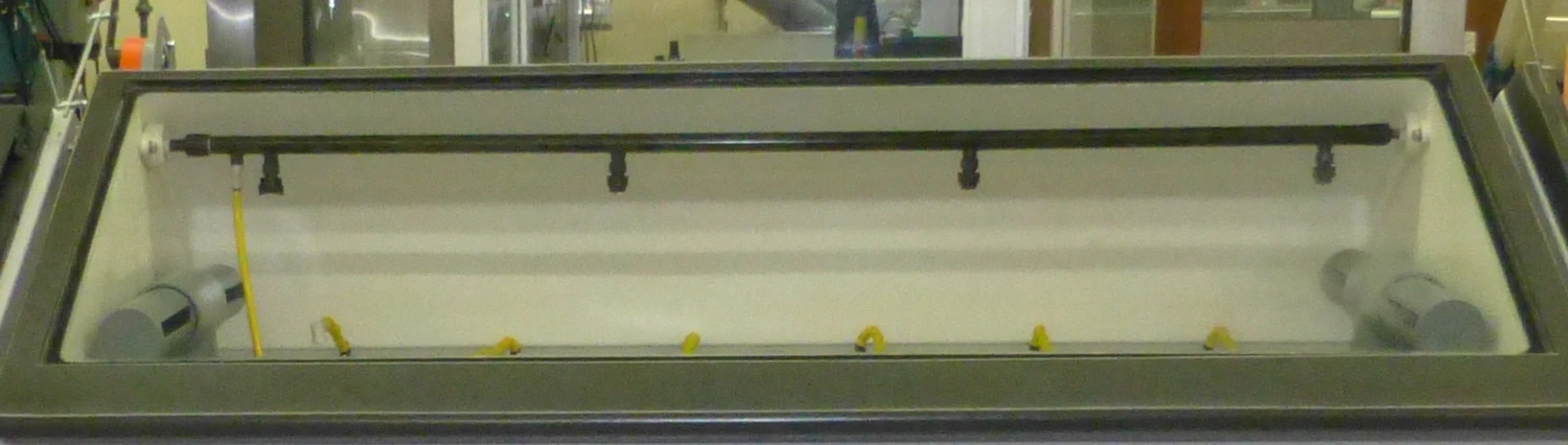
Swaying Spray Bar
The spray bar moves overlapping nozzle patterns across the specimen area to distribute the 0.5% NaCl solution. Ford identifies a moving spray device, such as a swaying rail, as the most reliable means of obtaining uniform downfall.
PC sequencing places spray events near the beginning, middle, and end of the wet phase.
Advanced Climate Control
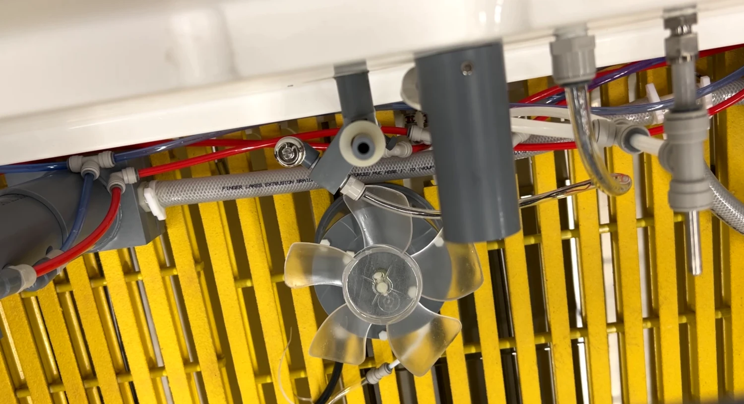
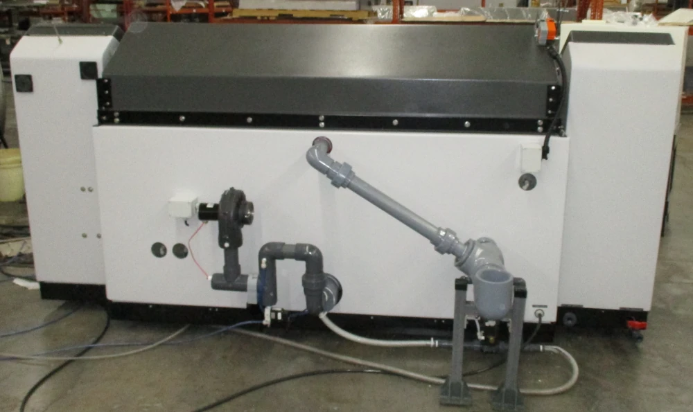
Advanced Climate Control combines RH sensing, cool-mist humidification, heating, dry-air dehumidification, air circulation, and auxiliary-blower cooling in one PC-controlled system. Together, these components perform the return from 50 °C to the 25 °C wet phase, humid heating, the two-hour drying ramp, and the 50 °C / 70% RH hold. The PC program coordinates the climate sequence and records temperature and RH setpoints and measured readings.
ATC measures temperature and RH in the center of the exposure zone, alongside the specimens. This gives the control system feedback from the actual exposure area instead of an isolated sensor location.
Verified Chamber Performance
The results below are actual records from Auto Technology’s validation testing of the X Series with Advanced Climate Control and the Swaying Spray Bar. The climate chart shows three cycles using the selected starting points. The six-week gauge-loss measurements and one- and two-week mass-loss results show the corrosion produced on exposed panels and coupons.
Verification checks that the chamber works as intended. Auto Technology evaluates the recorded temperature and humidity cycle together with the corrosion response of the verification panels. The climate records show the programmed exposures and transitions; the gauge-loss results check the combined effect of spray, temperature, humidity, drying, and airflow on the panels.
Temperature & RH Across the Recorded Cycles
Each cycle view runs from its selected starting point to the next cycle’s starting point. Brief sensor disturbances during compressed-air blow-off are corrected in both curves.
The transition view shows the recorded heating and drying ramps. Times are measured from the selected cycle’s starting point.
The cooling view shows the recorded return from 50 °C before the next cycle’s starting point. Its clock starts at the beginning of that cooling sequence, with Ford’s 30-minute and one-hour checkpoints marked.
Gauge Measurements & Corrections
Ford verification panels are exposed for six weeks, then removed, cleaned, and measured outside the chamber. Corrected gauge loss measures the corrosion severity produced by the exposure.
The validation exposure included approximately 30 lb of stainless steel to simulate a loaded chamber and check temperature and humidity transitions.
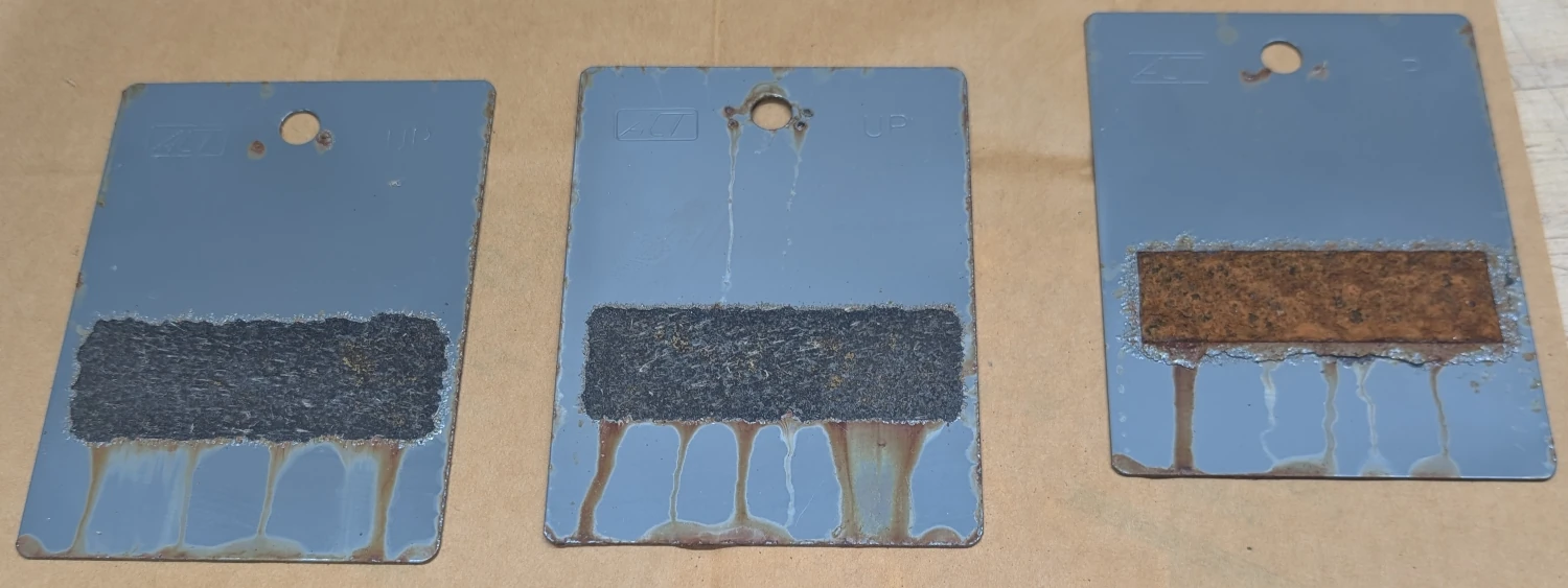
Auto Technology coupon locations. ATC placed verification panels at the left, middle, and right of the chamber to compare the corrosion response across those positions.
Each panel has six reference-area readings and twelve corroded-area readings. The table shows their means and standard deviations, the corrections applied, and the maximum corrected sector loss. Corrected net gauge loss is the reference-area mean minus the corroded-area mean, plus the 31 µm rust correction and minus the 5 µm E-coat correction. Ford’s target is 150–250 µm for each panel average.
| Measurement / calculation (µm) | Left | Middle | Right |
|---|---|---|---|
| Reference-area mean | 766.7 | 770.0 | 770.0 |
| Reference-area standard deviation | 5.16 | 0.00 | 0.00 |
| Corroded-area mean | 640.0 | 617.5 | 600.0 |
| Corroded-area standard deviation | 10.44 | 41.81 | 22.96 |
| Uncorrected difference | 126.7 | 152.5 | 170.0 |
| Rust correction | 31.0 | 31.0 | 31.0 |
| E-coat correction | -5.0 | -5.0 | -5.0 |
| Corrected net gauge loss | 152.7 | 178.5 | 196.0 |
| Maximum corrected sector loss | 176.0 | 236.0 | 226.0 |
View all 54 individual thickness readings
All thickness readings are in µm.
| Reference-area reading | Left | Middle | Right |
|---|---|---|---|
| 1 | 770 | 770 | 770 |
| 2 | 760 | 770 | 770 |
| 3 | 760 | 770 | 770 |
| 4 | 770 | 770 | 770 |
| 5 | 770 | 770 | 770 |
| 6 | 770 | 770 | 770 |
| Corroded-area reading | Left | Middle | Right |
|---|---|---|---|
| 1 | 650 | 640 | 610 |
| 2 | 650 | 650 | 590 |
| 3 | 650 | 580 | 590 |
| 4 | 650 | 640 | 600 |
| 5 | 640 | 560 | 590 |
| 6 | 630 | 580 | 590 |
| 7 | 640 | 640 | 610 |
| 8 | 620 | 690 | 630 |
| 9 | 630 | 590 | 570 |
| 10 | 640 | 630 | 650 |
| 11 | 630 | 650 | 600 |
| 12 | 650 | 560 | 570 |
Supplemental Mass-Loss Results
Additional coupons exposed alongside the gauge-loss panels produced the following mean mass losses. Each average represents two coupons.
| Exposure set | Duration | Mean mass loss (g) |
|---|---|---|
| One-week set 1 | 1 week | 0.8349 |
| One-week set 2 | 1 week | 0.9394 |
| Two-week set | 2 weeks | 1.7249 |
| One-week set 3 | 1 week | 1.0578 |
Ford Gauge-Loss Requirements: Tools & Measurements
Auto Technology uses ultrasonic thickness measurements to evaluate the steel lost from Ford verification panels after exposure. Ford TM 00.00-L-467 references FLTM CA 006-01 for ultrasonic measurement and FLTM CA 005-01 for the alternative micrometer method. CA 006-01 covers panels exposed under either L-467 or R-343.
Auto Technology Measurement Equipment
| Tool | Auto Technology Uses |
|---|---|
| Ultrasonic thickness gauge | Olympus 38DL Plus |
| Probe model | M208-RM |
| Panel holder and measurement template | Supports the coupon and locates the probe at the measurement points. |
| Couplant | Glycerin couplant between the probe and the coated measurement surface. |
Measurements from the Coated Back of the Panel
Auto Technology measures through the fully coated back of each panel, using the template to distribute readings across the two measurement areas. Following CA 006-01, six reference-area readings are taken opposite an area coated on both sides, and twelve corroded-area readings are taken opposite the exposed corrosion area. Measurements are recorded when the reading is stable and repeatable.
The reference-area mean is compared with the corroded-area mean to calculate the uncorrected thickness difference. The E-coat correction accounts for the different number of coating layers in the two measurement areas. CA 006-01 determines that correction using an untested panel from the same coating group.
Applying the Measurement Corrections
Auto Technology applies the E-coat correction determined for the panel group and the rust correction where applicable under CA 006-01. The applied corrections and corrected results for each panel appear in the gauge-loss table above.
This check verifies the corrosion response produced by the chamber. The six-week verification exposure does not set the required duration for every customer's component test; that duration comes from the governing Ford component or material requirement.
Configure an X Series for Your Ford L-467 Program
Send your specimen dimensions, quantity, total mass, loading arrangement, and Ford test requirement. ATC can specify the chamber size, Advanced Climate Control package, Swaying Spray Bar, and supports for your exposure.