710130 – HUMIDIFYING TOWER ASSEMBLY-CCT-NC
$3,140.68
CCT Chamber Part: HUMIDIFYING TOWER ASSEMBLY-CCT-NC.
- Part Number: 710130
- Category: CCT Chamber Part
- Use Case: Cyclic corrosion chamber service and maintenance
Description
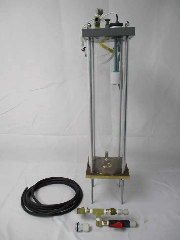
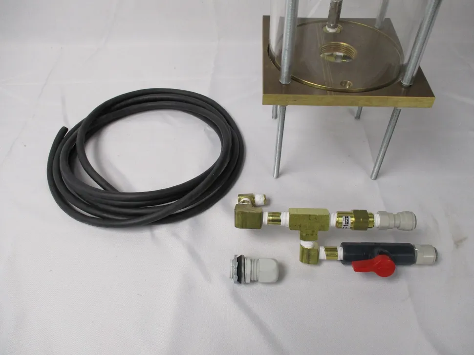
710130 – HUMIDIFYING TOWER ASSEMBLY-CCT-NC – Works with all Harshaw, Engelhard, Atotech USA, Atlas and Auto Technology Company fog and cyclic corrosion test chambers. The Bubble Tower is also referred to by other names – Humidifying Tower, Saturator Tower. Through-out Auto Technology documents it is referred to as a Bubble Tower, or BT. The purpose of the Bubble Tower is to provide conditioned (hot and humid) air to the atomizer nozzle/s. Conditioning the air before using it to atomize an electrolyte is an integral portion of many corrosion specifications, such as ASTM B117 and ISO9227. The bubble tower is mounted on the component plate in the control cabinet. T is found by removing the front access panel on the control cabinet. When removed, the bubble tower is visible. It is located in the back right corner of the control cabinet. The bubble tower is a self contained unit with three control loops. 1. Temperature control The temperature of the BT is set by the user in the cabinet controls. The controls compare the actual temperature to the set-point, and turn the BT heater ON and OFF as needed to maintain the set-point. 2. Water level control The water level of the BT is controlled by the BT float switch. During a FOG cycle, Solenoid # 5 allows compressed air to enter the bottom of the BT. As long as the BT float detects a FULL condition, Solenoid #5 remains ON. When the BT float reads a LOW condition, then Solenoid #5 is temporarily turned OFF to depressurize the BT. At the same time, Solenoid # 1 turns ON to allow the customer supplied pressurized DI water to enter the BT. When a FULL condition is detected, an internal timer starts counting to slightly over-fill the BT by X seconds (the time of X is set by the factory on the password -protected OEM set-up page; this is typically 3-5 seconds). When the timer has expired, Solenoid #1 turns OFF stopping DI water flow, and Solenoid #5 is reactivated to an ON position to allow compressed air to enter the BT. This sequence of events usually takes 5-10 seconds, depending on DI water pressure. The lower the DI water pressure, the longer this fill will take. 3. Air relief The air relief valve is a safety device to prevent the BT from over pressurizing and potentially bursting. This valve is usually set for 25 – 30psi / 172-207kPa at the factory. To adjust the relief valve, turn on the air to the BT. Using the BT air regulator, increase the air pressure to 25psi / 172kPa. If air is heard “hissing” from the air relief valve, it is properly relieving the pressure. If air escapes at a lower pressure, lift the cap on the air relief valve and adjust the knob until the hissing has just stopped. If air does not escape from the air relief valve when the BT air regulator is set to 25psi / 172kPa, lift the cap on the air relief valve and adjust the knob until the hissing has just started.
Additional information
| Weight | 25 lbs |
|---|---|
| Dimensions | 30 × 14 × 14 in |
Related products
-

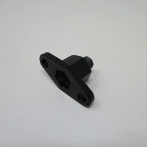
C260130 – REGULATOR MTG BRKT RRP95591
$52.03 Add to cart -
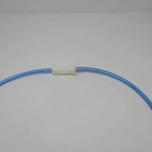
710300 – WATER FILITER ASSEMBLY
$23.88 Add to cart -
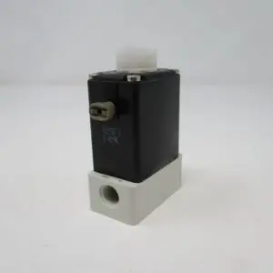
C212641 – SOLENOID 2 WAY PLASTIC VALVE – THIS SOLENOID IS FOR CHAMBERS BUILT PRE SEPT 2024 – SEE BELOW FOR DETAILS
$961.88 Add to cart -
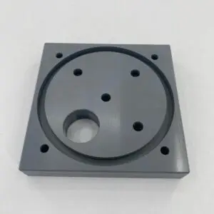
720345 – TOP PLATE 6″ BUBBLE TOWER (NC’S)
$244.71 Add to cart